
Ink-jet printing machine sprayer cleaning device and control method thereof

A technology of cleaning device and control method, applied in printing and other directions, can solve the problems of incomplete cleaning and low cleaning efficiency, and achieve the effects of thorough cleaning, strong versatility and less waste liquid

Pending Publication Date: 2019-01-11
GUANGZHOU EC PACK PACKAGING EQUIP
View PDF0 Cites 6 Cited by
  • Summary
  • Abstract
  • Description
  • Claims
  • Application Information

AI Technical Summary

Problems solved by technology

[0007] The purpose of the present invention is to solve the problems of incomplete cleaning and low cleaning efficiency caused by the manual cleaning in the above-mentioned prior art, and propose a cleaning device and control method for the spray head of the inkjet printer, which can effectively improve the cleaning efficiency

Method used


Image

  • Ink-jet printing machine sprayer cleaning device and control method thereof
  • Ink-jet printing machine sprayer cleaning device and control method thereof
  • Ink-jet printing machine sprayer cleaning device and control method thereof

Examples


Embodiment 1

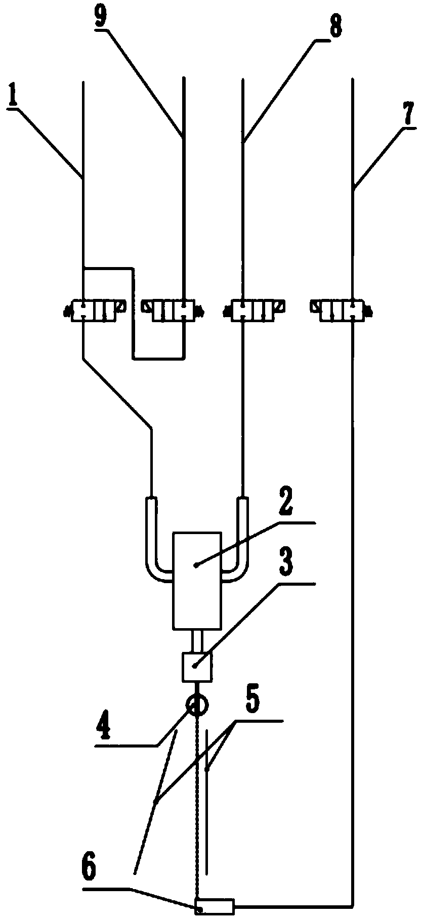
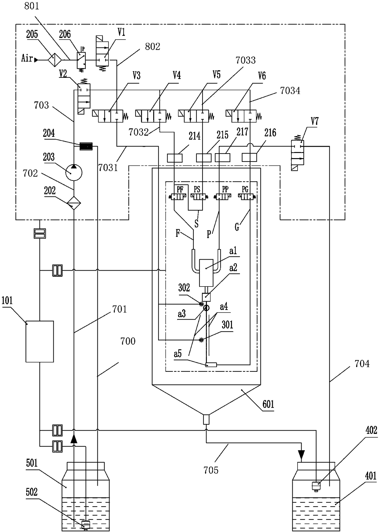
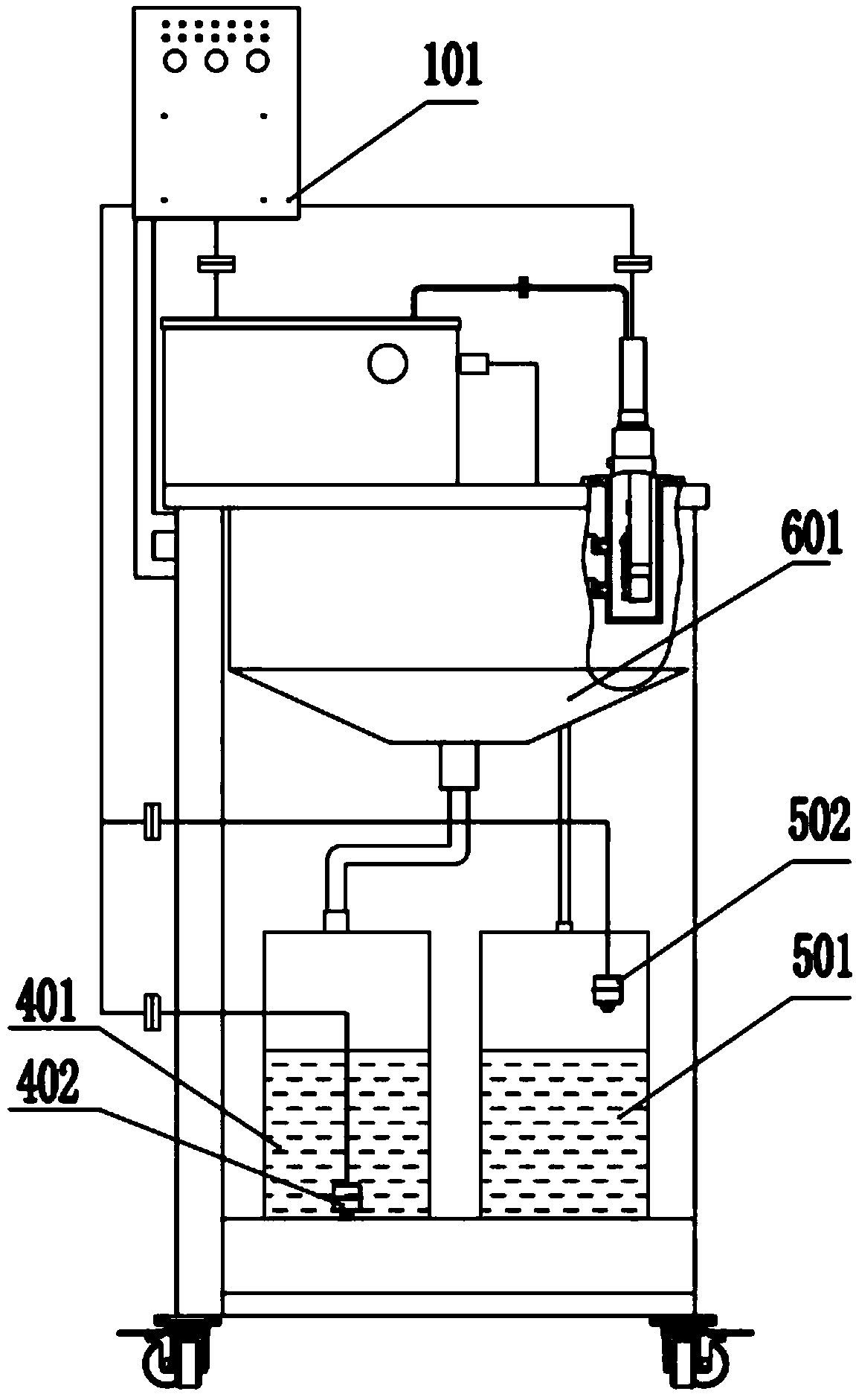
[0053] refer to Figure 2-Figure 4 , this embodiment provides a cleaning device for the inkjet printer nozzle, which is applied to the inkjet printer nozzle, and the inkjet printer nozzle includes a supply pipe F, an overflow pipe P, a recovery pipe G, a solvent pipe S, a spray chamber a1, Nozzle a2, charging electrode a3, deflection electrode pair a4, recovery tank a5 and circuit connection interface (not shown in the figure);

[0054] The supply pipe F is connected to one end of the spray chamber a1, the other end of the spray chamber a1 is connected to the overflow pipe P, the spray chamber a1 is fixedly connected to the nozzle a2, and the charging electrode a3, the deflection electrode pair a4 and the recovery tank a5 are arranged in cooperation with the nozzle a2 , the solvent pipe S is connected to the supply pipe F, the recovery pipe G is connected to the recovery tank a5, the supply valve PF is set on the supply pipe F, the overflow valve PP is set on the overflow pipe...

Embodiment 2

[0091] refer to Figure 2-Figure 4 , this embodiment provides a method for controlling the cleaning device of the inkjet printer nozzle, which is applied to the cleaning device of the inkjet printer nozzle described in Embodiment 1, and the method includes:

[0092] The control device 101 receives the start-up command, and controls the first liquid level gauge 502, the second liquid level gauge 402 and the air pressure switch 206 to collect the first liquid level information of the cleaning liquid tank 501 and the waste liquid recovery tank 401 according to the start-up command. The second liquid level information and the air pressure information on the first air circuit 801;

[0093] Judging whether the liquid level in the cleaning liquid tank 501 is higher than the first preset liquid level according to the first liquid level information, and judging whether the liquid level in the waste liquid recovery tank 401 is lower than the second preset liquid level according to the s...


PUM


Abstract

The invention provides an ink-jet printing machine sprayer cleaning device and a control method thereof. The cleaning device comprises a first adaptive pipe connector, a second adaptive pipe connector, a third adaptive pipe connector, a fourth adaptive pipe connector, a cleaning solution filter, a pump, a backpressure pipe, an air filter, an air pressure switch, an atomizing nozzle, a cleaning solution tank, a first liquidometer, a collection groove, a waste solution recycling tank, a second liquidometer and a control device. By arranging the different adaptive pipe connectors, the ink-jet printing machine sprayer cleaning device can be suitable for different factories to produce ink-jet printing machines, universality is high, printing machine sprayers and other components are automatically washed, the washing process is conducted in a closed mode, waste cleaning solutions are automatically collected, generated waste liquid is little, manual work is not needed, and safety and high efficiency are achieved.

Description

technical field [0001] The invention relates to a cleaning device and a control method for a spray head of an inkjet printer. Background technique [0002] Continuous inkjet printers (CIJ) can print the required information on most products. These data can be time, date, production code, barcode, QR code, consumer information or manufacturer's logo, product tracking information and other information, etc. Widely used in medicine, chemical industry, food, building materials, tobacco, ceramics, electronics and other industries. [0003] A continuous inkjet printer (CIJ) generally consists of a main chassis and one or more nozzles. The chassis is equipped with electronic components, ink system, power supply module, display screen or keyboard, etc. The nozzle is generally connected to the main chassis through a flexible conduit, and the nozzle pipeline and cables are placed in the conduit. [0004] refer to figure 1 , the working principle of the inkjet printer is as follow...

Claims


Application Information

Patent Timeline
IPC IPC(8): B41J2/165
CPCB41J2/16552Y02P70/10
Inventor 颜学斌徐强李云峰蔡超秦嘉源
Owner GUANGZHOU EC PACK PACKAGING EQUIP
Learn More