Viscosity reduction treatment tank for oil pumping of oil well

A technology for treating tanks and pumping oil, which is applied in the petroleum industry, refined hydrocarbon oil, wellbore/well parts, etc. It can solve problems such as increased resistance of crude oil transportation, hidden dangers of pipeline transportation safety, and pipe condensation accidents, etc., to reduce viscosity The effect of improving the transmission efficiency and preventing potential safety hazards

Active Publication Date: 2019-01-11
HEILONGJIANG LANDE ULTRASONIC TECH CO LTD
View PDF2 Cites 6 Cited by
  • Summary
  • Abstract
  • Description
  • Claims
  • Application Information

AI Technical Summary

Problems solved by technology

However, when the crude oil is pumped to the wellhead, since the surface temperature is much lower than the temperature in the well, the temperature of the crude oil will gradually drop, and its viscosity will increase as the temperature drops, and the wax, asphaltenes and colloids in the crude oil will be deposited on the pipeline wall , so that the transportation resistance of crude oil increases and the output decreases
Under the action of adsorption force, the wax crystals adhere to the inner wall of the pipeline and deposit continuously. In severe cases, it may even cause a pipe condensation accident, which poses a great safety hazard to pipeline transportation.

Method used


Image

  • Viscosity reduction treatment tank for oil pumping of oil well
  • Viscosity reduction treatment tank for oil pumping of oil well
  • Viscosity reduction treatment tank for oil pumping of oil well

Examples


specific Embodiment approach 1

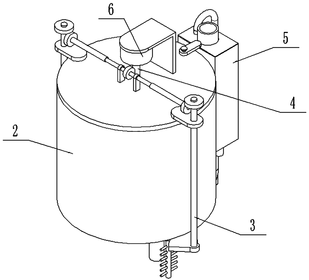
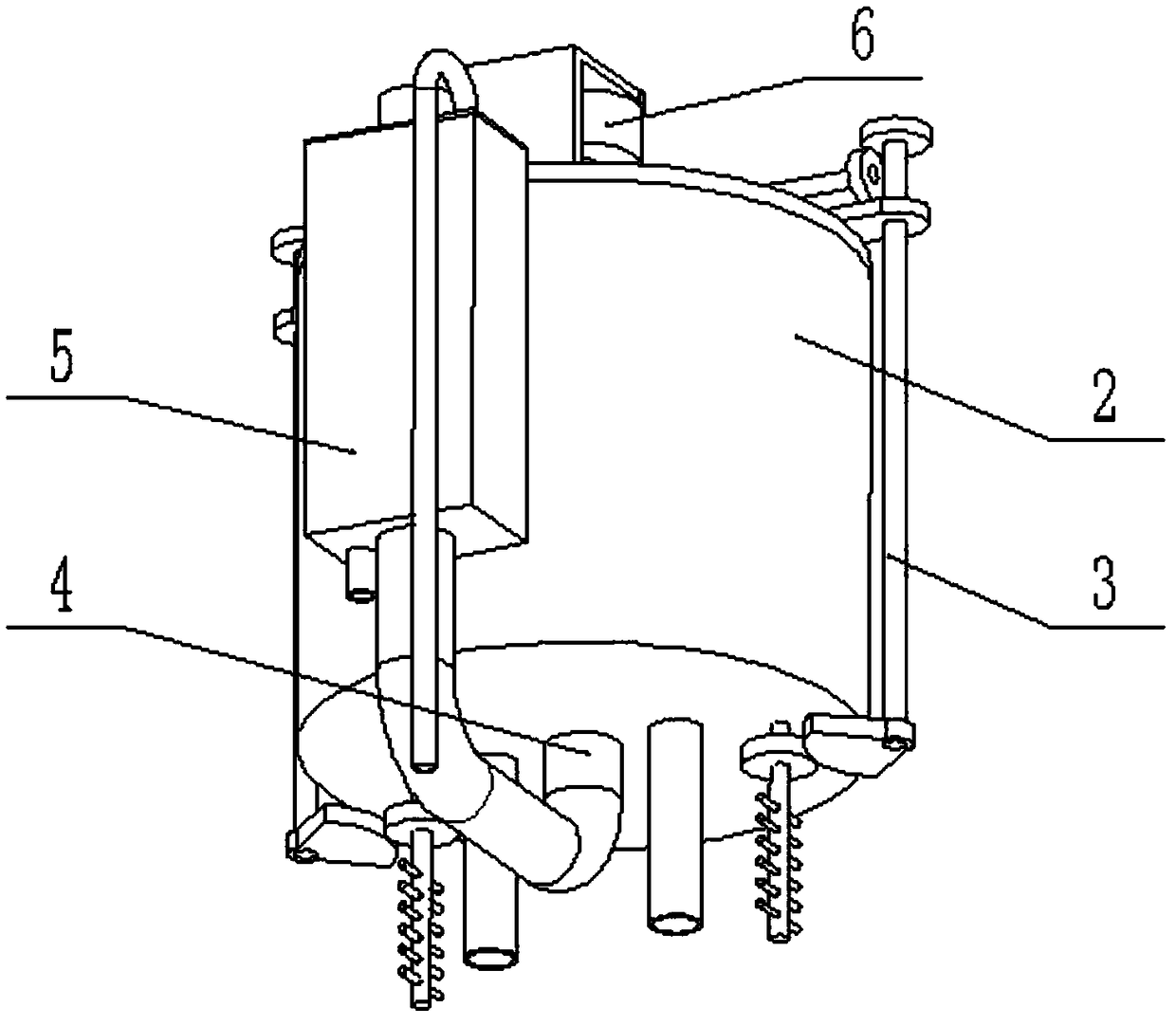
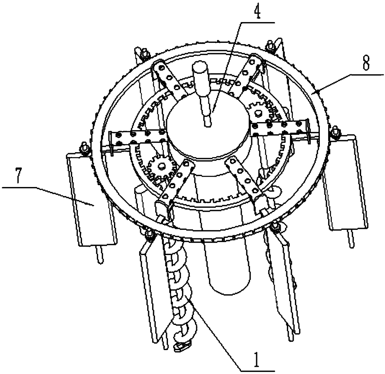
[0029] like Figure 1-11As shown, the viscosity reduction treatment tank for oil well pumping includes oil pump 1, treatment tank 2, stirring viscosity reduction mechanism 3, oil filter pipe 4, heat exchange viscosity reduction pipe 5, driving motor 6, rotary agitator 7 and transmission wheel 8; the treatment tank 2 includes a tank body 2-1, a tank cover 2-2 and an oil suction pipe 2-3; the top end of the tank body 2-1 is sealed and connected to the tank cover 2-2; the tank body 2-1 Both sides of the bottom end are respectively fixedly connected and communicated with an oil suction pipe 2-3; the oil extractor 1 is provided with two, and the upper ends of the two oil extractors 1 are all rotatably connected to the inner side of the tank body 2-1. The lower end of each oil extractor 1 is respectively connected to the inside of two oil extraction pipes 2-3; the upper end of the oil extractor 1 is meshed with the inner end of the transmission wheel 8, and the outer end of the tran...

specific Embodiment approach 2

[0030] like Figure 1-11 As shown, the oil pump 1 includes a sucker rod 1-1, a sucker screw 1-2, a rod seat 1-3, a swirl plate 1-4 and a driven gear 1-5; the sucker rod 1- 1. The driven gear 1-5, the swirl plate 1-4 and the oil suction screw 1-2 are fixedly connected in sequence from top to bottom; the driven gear 1-5 is meshed with the transmission wheel 8; the swirl plate 1-4 The rotation fit is connected to the inside of the tank body 2-1; the oil sucking screw 1-2 is connected to the inside of the oil suction pipe 2-3 and the tank body 2-1 with rotation fit; the lower end of the sucker rod 1-1 is passed through a belt The seat bearing is rotatably connected on the rod seat 1-3, and the rod seat 1-3 is fixedly connected on the inner wall of the oil extraction pipe 2-3.

[0031] When the oil pump 1 is in use, the driven gear 1-5 rotates under the drive of the transmission wheel 8, and when the driven gear 1-5 rotates, it can drive the sucker rod 1-1 to rotate, and the sucke...

specific Embodiment approach 3

[0032] like Figure 1-11 As shown, the oil filter pipe 4 includes a worm screw 4-1, a linkage shaft 4-2, a filter box 4-3, a straight oil delivery pipe 4-4, a plurality of rotating pipes 4-5 with filter holes on the surface, a vertical connection Plate 4-6 and oil delivery screw 4-7; the upper end of the worm 4-1 is connected to the output shaft of the drive motor 6 through a coupling; the lower end of the worm 4-1 is fixedly connected to the linkage shaft 4-2, and the linkage shaft 4-2 is sealed and rotated in the middle of the tank cover 2-2; the middle end of the linkage shaft 4-2 is fixedly connected in the middle of the filter box 4-3, and the lower end of the linkage shaft 4-2 is inserted into the straight oil pipe 4 -4; the lower end of the linkage shaft 4-2 is fixedly connected to the oil delivery screw 4-7, and the oil delivery screw 4-7 is rotated and connected to the inner side of the oil delivery straight pipe 4-4; the worm 4-1 drives Connect the stirring viscosit...


PUM


Abstract

The invention relates to the field of oil well oil pumping equipment and particularly relates to a viscosity reduction treatment tank for oil pumping of an oil well. The viscosity reduction treatmenttank comprises two oil pumping devices, a treatment tank, a stirring viscosity reduction mechanism, an oil filtering pipe, a heat-exchange viscosity reduction pipe, a driving motor, a rotary stirrer and a transmission wheel, wherein the treatment tank comprises a tank body, a tank cover and two oil pumping pipes; the tank cover is connected to the top end of the tank body in a sealing manner; theoil pumping pipe is fixedly connected and communicated to each of two sides of the bottom end of the tank body; the upper ends of the two oil pumping devices are rotatably and cooperatively connectedto the inner side of the tank body, and the lower ends of the two oil pumping devices are respectively connected to the inner sides of the oil pumping pipes; and the upper ends of the oil pumping devices are meshed and connected to the inner ends of the transmission wheel, and a plurality of rotary stirrers are in transmission connection to the outer end of the transmission wheel. According to theviscosity reduction treatment tank, multiple works of raw oil pumping, stirring viscosity reduction, oil liquid filtration, heat-exchange viscosity reduction and the like can be realized, the raw oilpumping efficiency is improved, and the viscosity of the raw oil is effectively decreased.

Description

technical field [0001] The invention relates to the field of oil well pumping equipment, in particular to a viscosity-reducing treatment tank for oil well pumping. Background technique [0002] In the process of mechanical oil recovery, crude oil is pumped from the high temperature downhole through the pumping unit to the ground and transported to the oil gathering station. Most of the oil quality of crude oil is heavy oil and extra heavy oil, which has many heavy components and high viscosity, and the viscosity decreases at high temperature. However, when the crude oil is pumped to the wellhead, since the surface temperature is much lower than the temperature in the well, the temperature of the crude oil will gradually drop, and its viscosity will increase as the temperature drops, and the wax, asphaltenes and colloids in the crude oil will be deposited on the pipeline wall , so that the transportation resistance of crude oil increases and the output decreases. Under the ...

Claims


Application Information

Patent Timeline
Patent Type & Authority Applications(China)
IPC IPC(8): C10G31/00C10G31/09E21B43/00E21B43/34
CPCC10G31/00C10G31/09E21B43/126E21B43/34
Inventor 侯晓丹单长城迟毅康宝义于秀荣
Owner HEILONGJIANG LANDE ULTRASONIC TECH CO LTD
Why Eureka
Try Eureka