
Parabolic wave energy utilization type breakwater

A technology of breakwater and parabola, applied in the directions of breakwater, jetty, embankment, etc., to achieve the effect of cost reduction, reasonable structure design and mature construction plan

Inactive Publication Date: 2019-01-11
DALIAN UNIV OF TECH
View PDF3 Cites 8 Cited by
  • Summary
  • Abstract
  • Description
  • Claims
  • Application Information

AI Technical Summary

Problems solved by technology

However, at present, the commercial application of various types of wave energy generation devices is still restricted by two important factors, namely, construction cost and conversion efficiency.

Method used


Image

  • Parabolic wave energy utilization type breakwater
  • Parabolic wave energy utilization type breakwater
  • Parabolic wave energy utilization type breakwater

Examples


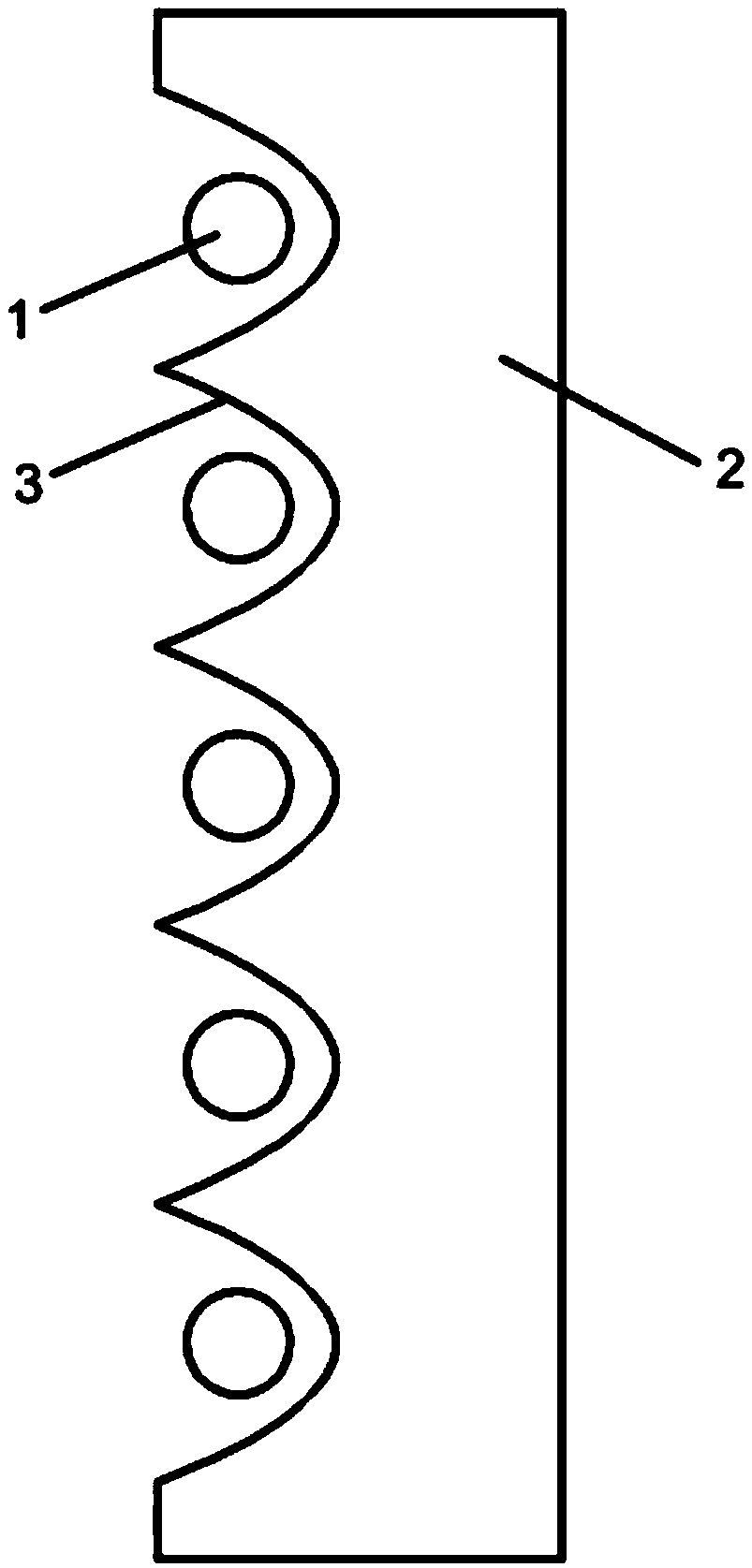
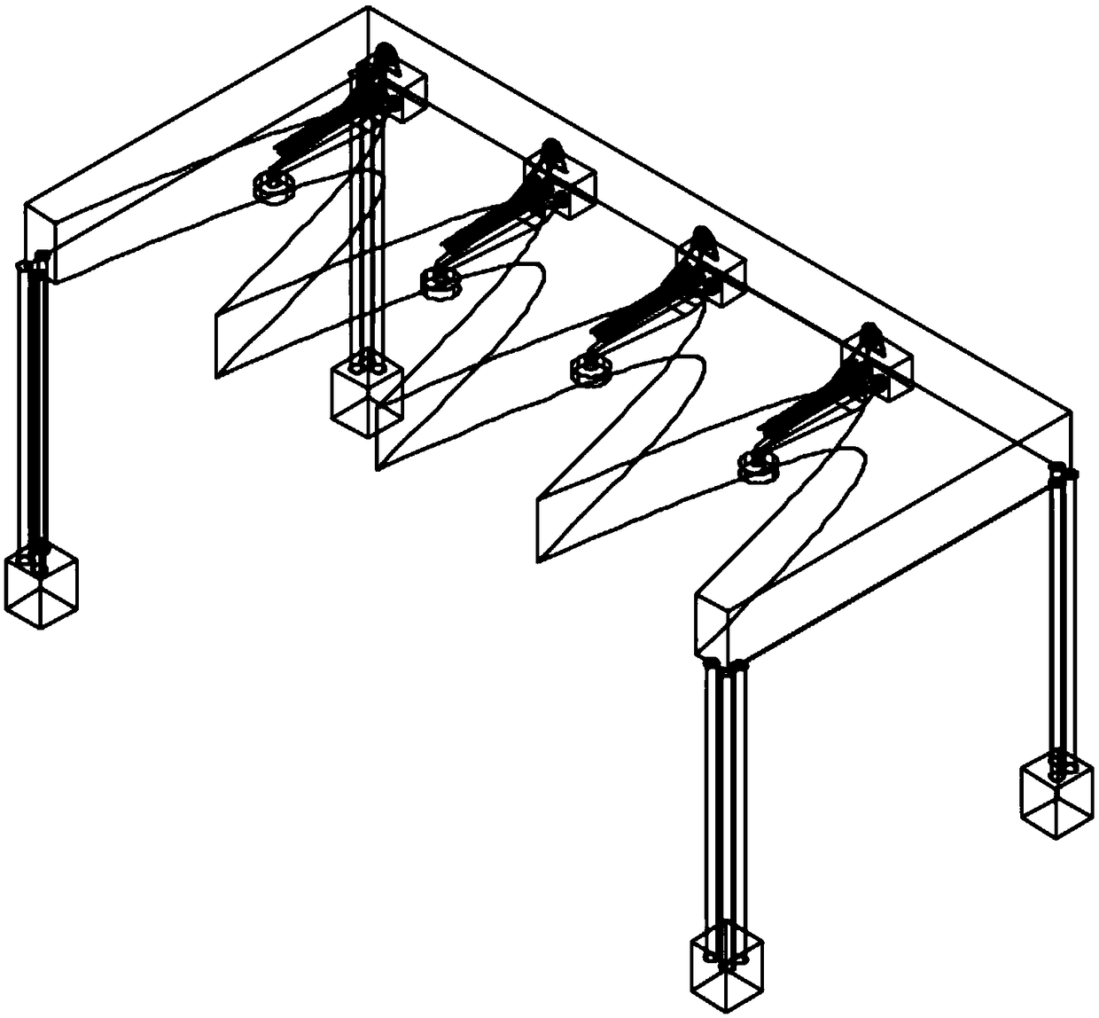
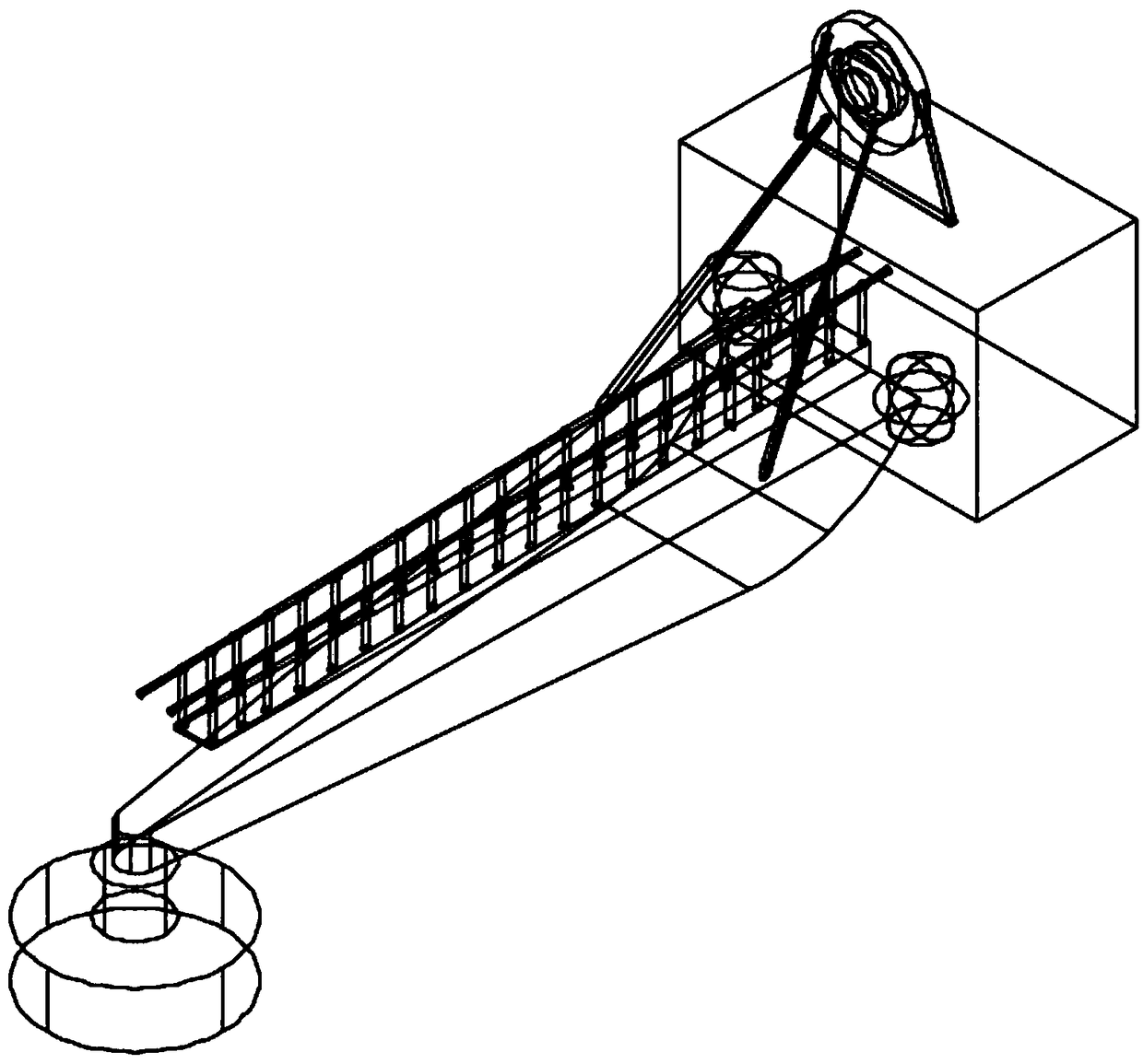
Embodiment Construction

[0027] The present invention will be further described below in conjunction with the accompanying drawings and specific embodiments.

[0028] A parabolic wave energy utilization breakwater includes a floating breakwater structure and an oscillating float type wave energy power generation device. The body of the breakwater is a floating breakwater structure with a parabolic opening array, and the wave energy generating device adopts an oscillating buoy type wave energy generating device. The floating breakwater structure includes a parabolic opening, a breakwater embankment, tension tendons, and anchoring structures. The oscillating buoy type wave energy generating device comprises a buoy, a supporting structure, a spherical hinge structure, an energy storage box, a generator, a hydraulic rod, and a walking channel. There is a parabolic opening on the wave facing surface of the breakwater, and the float is located at the focus of the parabolic opening of the breakwater. The f...


PUM


Abstract

The invention discloses a parabolic wave energy utilization type breakwater. The parabolic wave energy utilization type breakwater comprises a floating type breakwater structure with a parabolic opening array and an oscillating floater type wave energy power generation device. The parabolic opening array is arranged on a wave facing surface of the breakwater; waves come from open sea are reflectedto the focal position of each parabolic opening by an opening wall surface, so that wave energy is focused; and floater structures of the oscillating floater type wave energy power generation deviceare arranged at each focal position to maximize the energy which can be captured. The parabolic wave energy utilization type breakwater has the beneficial effects that the parabolic opening array is arranged on the wave facing surface of the breakwater, so that the wave energy can be focused at the focal positions in openings; floaters of the wave energy power generation device are mounted at thefocal points of the openings where the waves are focused so that the captured wave energy is maximized; the wave energy power generation and a breakwater structure are integrated, so that wave can beprevented, and the wave energy can also be collected; and therefore, the cost for constructing the breakwater and the wave energy power generation device is reduced. The novel integrated power generation structure system can be widely applied to the development of wave energy resources.

Description

technical field [0001] The invention belongs to the technical field of ocean energy utilization, in particular to a device for comprehensive utilization of coastal protection and wave energy. Background technique [0002] Since the first oil crisis in 1974, people have started to develop renewable energy technologies, such as clean energy conversion technologies such as wind energy, solar energy and ocean energy. As a kind of ocean energy with great development potential, wave energy has continuously attracted the attention of researchers in recent decades. People have proposed more than a thousand kinds of wave energy generating devices at present. However, at present, the commercial application of various wave energy generating devices is still restricted by two important factors, namely, construction cost and conversion efficiency. [0003] In order to break through the above two constraints of the commercialization of wave energy devices, researchers in the field of co...

Claims


Application Information

Patent Timeline
IPC IPC(8): E02B3/06E02B9/08F03B13/18
CPCE02B3/06E02B3/062E02B9/08F03B13/1815Y02E10/30
Inventor 张崇伟孙小童宁德志梁丙臣
Owner DALIAN UNIV OF TECH
Learn More