Fast-disassembly formwork fixing system and fixing method in fixing system

A formwork fixing and fixing method technology, applied in formwork/formwork/work frame, processing of building materials, preparation of building components on site, etc. The effect of reducing the labor intensity of workers, avoiding the spread of iron chips, and reducing work intensity

Pending Publication Date: 2019-01-11
付志红 +1
View PDF10 Cites 1 Cited by
  • Summary
  • Abstract
  • Description
  • Claims
  • Application Information

AI Technical Summary

Problems solved by technology

The fixation between the existing formworks is to fix the longitudinal wooden squares to the lower part of each formwork through iron dings. When the formwork is removed, it is very dangerous and cumbersome. easy to drop uncontrollably), then remove the steel pipe or square wooden dragon tendon, and finally remove the wooden square and formwork. Stabbing workers can easily cause tetanus, which brings great risks to workers and is not conducive to normal construction

Method used


Image

  • Fast-disassembly formwork fixing system and fixing method in fixing system
  • Fast-disassembly formwork fixing system and fixing method in fixing system
  • Fast-disassembly formwork fixing system and fixing method in fixing system

Examples


Embodiment 1

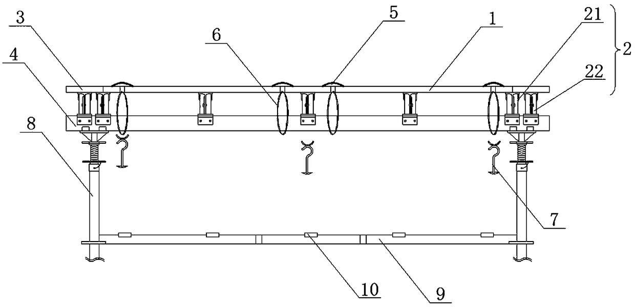
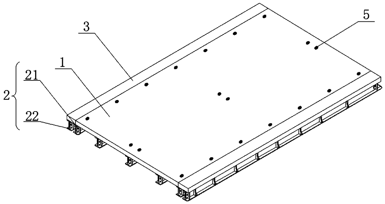
[0040] This embodiment provides a splicing unit structure, such as figure 1 , figure 2As shown, the splicing unit includes a complete quick release formwork 1, the length of the quick release formwork is 2400mm, and the width is 850~1103mm. The lower part of the quick release formwork 1 is evenly arranged longitudinally with five parallel secondary reinforcement corrugations 2, and the five secondary reinforcement corrugations 2 include two connection corrugations 21 on the sides of the quick release formwork, and three evenly distributed and arranged on the two connection corrugations. The erection method of supporting flute 22 between 21 and three connection flutes 21 is to get the central point and two ends of the main reinforcement flute 4, respectively fix the secondary reinforcement flute 2, and then fix the connection flute 21 at the midpoint of each section in turn. The two sides of the quick-release formwork 1 are closely attached to the same quick-release rear stri...

Embodiment 2

[0044] This embodiment provides a splicing unit structure, such as figure 1 , figure 2 As shown, the splicing unit includes a complete quick release formwork 1, the length of the quick release formwork is 2400mm, and the width is 850~1103mm. The lower part of the quick release formwork 1 is evenly arranged longitudinally with five parallel secondary reinforcement corrugations 2, and the five secondary reinforcement corrugations 2 include two connection corrugations 21 on the sides of the quick release formwork, and three evenly distributed and arranged on the two connection corrugations. 21 between the support corrugated 22. The two sides of the quick-release formwork 1 are closely attached to the same quick-release rear strip support plate 3, and the lower part of the joint between the quick-release strip support plate 3 and the quick-release formwork 1 uses the same connecting groove 21, and the quick-release rear strip support The lower part of the plate 3 is also provid...

Embodiment 3

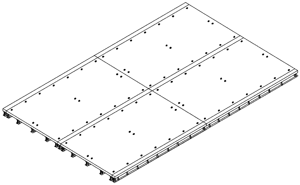
[0048] This embodiment provides a splicing unit structure, such as figure 1 , Figure 4 As shown, the splicing unit includes a quick-release template 1 composed of two target plates, the length of which is 2400mm, the width of the two target plates is 350~853mm, and the width of a single target plate is 850~1103mm . In this embodiment, in order to simplify the structure of the target boards, it is particularly preferred that the widths of the two target boards are exactly the same, but this does not mean that it is not possible to choose to use different widths of the target boards to form the quick-release template 1 .

[0049] The lower parts of the two standard boards are longitudinally and evenly arranged with five parallel secondary reinforcement flutes 2, and the five secondary reinforcement flutes 2 include two connecting flute 21 on the side of the quick-release formwork, and one common at the junction of the two standard boards. Connecting flute 21, and two supporti...


PUM


Abstract

The invention discloses a fast-disassembly formwork fixing system, mainly comprising a plurality of stitching units which are closely, regularly and fixedly stitched together. Each stitching unit includes a plurality of primary reinforcement ribs arranged according to the shape of Everest and a plurality of secondary reinforcement ribs longitudinally arranged in the upper parts of the primary reinforcement ribs. A fast-disassembly formwork is arranged above the secondary reinforcement ribs. A number of fixing pins distributed regularly are embedded into the fast-disassembly formwork, the nut ends of the fixing pins are exposed on the upper surface of the quick-disassembly formwork, and the pin head ends penetrate the quick-disassembly formwork to be fixedly equipped with elastic rubber bands. Hooks matching the elastic rubber bands are arranged in the lower part of the quick-disassembly formwork. The hooks hook at least one elastic rubber band to fix the quick-disassembly formwork andthe secondary reinforcement ribs together. A clamp slot is arranged in the top of the hook end of each hook. The invention provides a fast-disassembly formwork fixing system, which makes fast-disassembly formworks fixed together without using too much wood squares and iron nails, greatly reduces the fixing cost of fast-disassembly formworks, and reduces the risk of workers being pinned by iron nails. The fast-disassembly formwork fixing system is simple in structure, convenient to use and suitable for wide promotion and application.

Description

technical field [0001] The invention relates to the technical field of building construction equipment, in particular to a quick-release formwork fixing system and a fixing method in the fixing system. Background technique [0002] In the construction of concrete buildings, in order to ensure that the concrete structure is poured and formed according to the design requirements, a temporary model structure composed of building templates and wooden squares is usually used. As for the concrete building structure, when forming the structure, it is necessary to construct a formwork frame structure corresponding to the design size and shape. In the floor support system, when the quick-release formwork is used as a longitudinal building structure formwork, several formworks need to be spliced ​​together. In order to maintain the stability of the poured concrete, the formwork needs to be fixed. The fixation between the existing formworks is to fix the longitudinal wooden squares to...

Claims


Application Information

Patent Timeline
Patent Type & Authority Applications(China)
IPC IPC(8): E04G11/36E04G11/48E04G21/00
CPCE04G11/36E04G11/48E04G21/00
Inventor 付志红
Owner 付志红
Why Eureka
Try Eureka