Filling adaptive water control screen pipe

A self-adaptive, water-screening technology, applied in the fields of production fluids, wellbore/well components, earth-moving drilling, etc., which can solve the problems of increasing the filling displacement, the inability to pass the displacement, and the inability of the passive flow control valve to be adjusted.

Active Publication Date: 2019-01-11
CHINA NAT OFFSHORE OIL CORP +1
View PDF10 Cites 6 Cited by
  • Summary
  • Abstract
  • Description
  • Claims
  • Application Information

AI Technical Summary

Problems solved by technology

[0004] 1. In the solid particle filling process, in order to ensure the carrying effect of the filling liquid, it is usually necessary to increase the filling displacement, and the flow control structure on the water control screen adopts the principle of small holes or flow channel throttling, which cannot pass through larger Displacement, fil

Method used


Image

  • Filling adaptive water control screen pipe
  • Filling adaptive water control screen pipe
  • Filling adaptive water control screen pipe

Examples


Embodiment 1

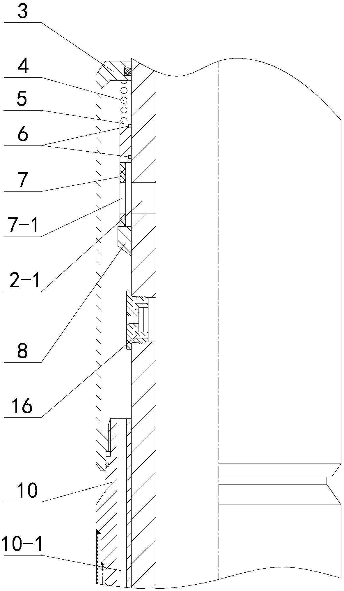
[0029] Such as figure 2 and image 3 As shown, this embodiment discloses a fillable self-adaptive water control screen. On the basis of the above water control screen in the prior art, an adaptive flow control valve 16 is used to replace the passive flow control valve 9, and an additional Large displacement filling hole 2-1 and self-resetting filling mechanism.

[0030] The self-adaptive flow control valve 16 can adopt a viscosity-sensitive flow control valve disclosed in the Chinese patent whose publication number is CN105840894B. Make adaptive adjustments.

[0031] The large-displacement filling hole 2-1 is set on the side wall of the base pipe 2 above the adaptive flow control valve 16, and is used to allow the filling fluid to enter the interior of the base pipe 2 and circulate out of the well after passing through the large-displacement filling hole 2-1. Large displacement filling hole 2-1 can meet 2m 3 Filling displacement requirements within / min.

[0032]The self...

Embodiment 2

[0036] Such as Figure 4 and Figure 5 As shown, this embodiment discloses a fillable self-adaptive water control screen. On the basis of the above water control screen in the prior art, an adaptive flow control valve 16 is used to replace the passive flow control valve 9, and an additional Large displacement filling hole 2-1 and water-swellable rubber 17.

[0037] Both the self-adaptive flow control valve 16 and the large displacement filling hole 2-1 are completely the same as those in the first embodiment. The difference from Embodiment 1 is that the water-swellable rubber 17 is used instead of the self-resetting filling mechanism.

[0038] The water-swellable rubber 17 is arranged in the annular space between the base pipe 2 and the valve shield 3, and is glued and fixed on the inner rotary surface of the valve shield 3, and is located at the large displacement filling hole 2-1 and the self-adaptive flow control valve Between 16. The water-swellable rubber 17 can adopt...


PUM


Abstract

The invention belongs to the oil and gas exploration technology field and discloses a filling adaptive water control screen pipe. A base pipe in a valve shield is provided with a large displacement filling hole and an adaptive flow control valve. The external portion of the large displacement filling hole is provided with a self-reset filling mechanism. Or a water-swelling rubber is arranged in anannulus between the base pipe and the valve shield. The self-reset filling mechanism is formed by a spring, a slide sleeve, a sealing ring, a soluble support sleeve and a positioning ring. When the soluble support sleeve supports the slide sleeve, the large displacement filling hole is in an open state. After the soluble support sleeve is corroded by water, the slide sleeve closes and seals the large displacement filling hole. After the water-swelling rubber is swelled in the water, a filling channel between the overflow hole channel of an overflow end ring and the large displacement fillinghole of the base pipe is closed. In the invention, the adaptive flow control valve and a large displacement filling mechanism are effectively combined in the screen pipe so that the large displacementdemand of filling work is satisfied and effective sand prevention and water control during a production process can be realized; and a water control completion effect is effectively improved, and a water control validity period is prolonged.

Description

technical field [0001] The invention belongs to the technical field of petroleum and natural gas exploitation, and in particular relates to an adaptive water control screen. Background technique [0002] In the process of oil and gas development, in order to increase the drainage area of ​​the production layer and realize the development of oil reservoirs under low production pressure difference, horizontal wells are often used for development. Due to reservoir heterogeneity, heel-toe effect, and fluid property differences, it is easy to cause early water breakthrough and rapid rise of water cut in horizontal wells. Excessive water cut in the oil well will slow down the oil production rate, and the oil field has to adopt the method of increasing the liquid production rate to maintain the production ratio index, and the huge liquid production rate increases energy consumption and increases the load of the platform water treatment equipment. It is easy to erode the sand contr...

Claims


Application Information

Patent Timeline
IPC IPC(8): E21B43/08
CPCE21B43/086
Inventor 邢洪宪王丙刚张纪双张云驰王尧张春升李瑞丰刘传刚刘景超董海宽罗晓青
Owner CHINA NAT OFFSHORE OIL CORP
Why Eureka
Try Eureka