Real-time control system of magnetic suspension electric main shaft and magnetic suspension electric main shaft

A magnetic levitation motorized spindle, real-time control system technology, applied in the direction of shaft and bearing, bearing, mechanical equipment, etc., can solve the problems of inability to realize online test and adjustment of control system parameters, poor control effect, low adjustment efficiency, etc. Control accuracy and regulation efficiency, shorten the development cycle, and achieve low-cost effects

Active Publication Date: 2019-01-11
HUAZHONG UNIV OF SCI & TECH
View PDF10 Cites 2 Cited by
  • Summary
  • Abstract
  • Description
  • Claims
  • Application Information

AI Technical Summary

Problems solved by technology

Due to the complexity of the structure of the magnetic levitation electric spindle, the real-time monitoring and parameter adjustment efficiency of the state of the magnetic levitation electric spindle in the existing technology is relatively low, and the control effect is not good
The current real-time simulation control system on the market can improve efficiency, but these devices are expensive, and the cost of using these devices as a control system for a magnetic levitation electric spindle is relatively high
In addition, in the existing control system of the magnetic levitation electric spindle, the online test and adjustment of the internal parameters of the control system cannot be realized.

Method used


Image

  • Real-time control system of magnetic suspension electric main shaft and magnetic suspension electric main shaft
  • Real-time control system of magnetic suspension electric main shaft and magnetic suspension electric main shaft

Examples


Embodiment Construction

[0029] In order to make the object, technical solution and advantages of the present invention clearer, the present invention will be further described in detail below in conjunction with the accompanying drawings and embodiments. It should be understood that the specific embodiments described here are only used to explain the present invention, not to limit the present invention. In addition, the technical features involved in the various embodiments of the present invention described below can be combined with each other as long as they do not constitute a conflict with each other.

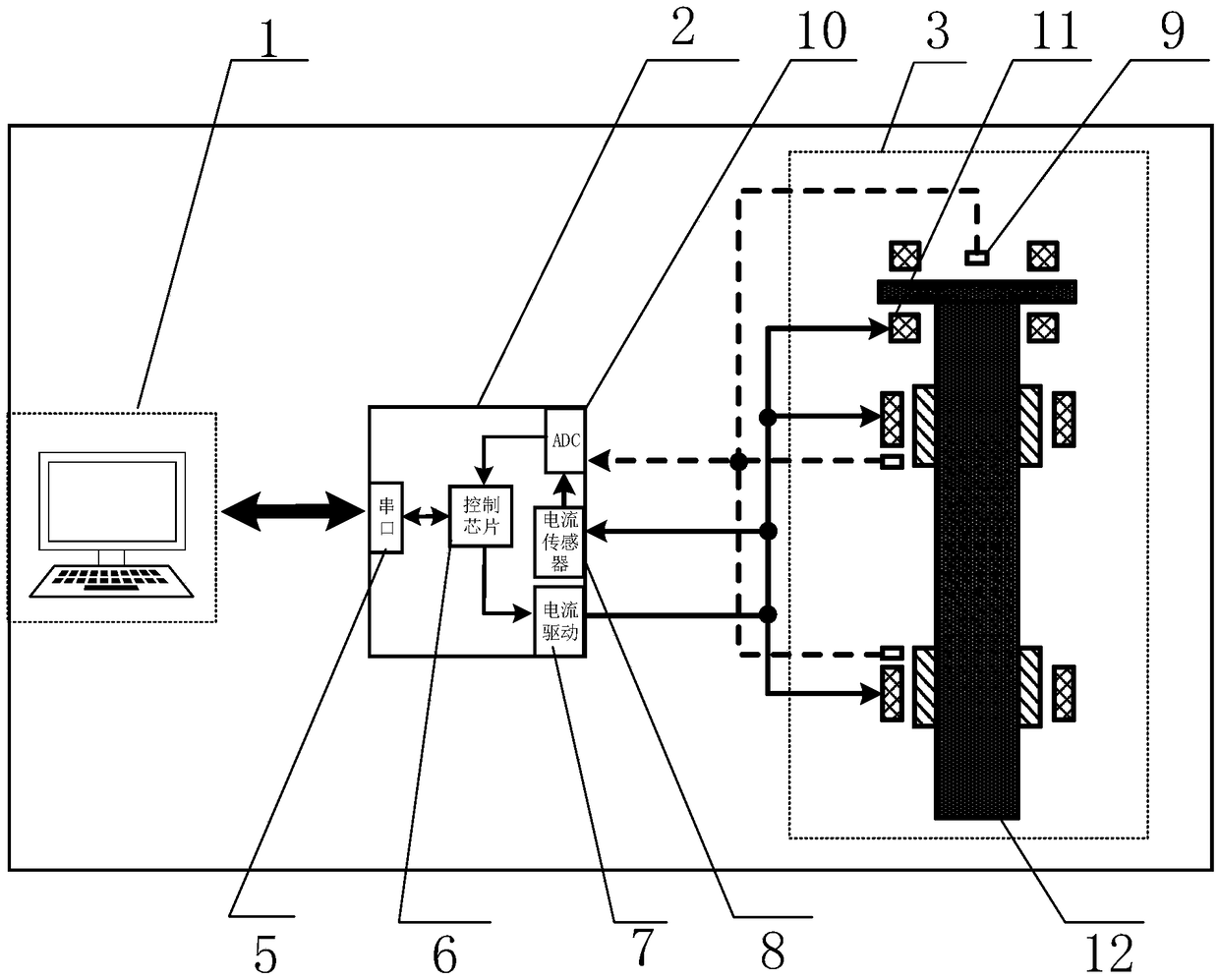
[0030] Before introducing the technical solution of the present invention in detail, the basic structure of the magnetic levitation electric spindle is briefly introduced. The magnetic levitation electric spindle includes a magnetic levitation bearing with five degrees of freedom. These five degrees of freedom are specifically: the front x, y axis, the rear x, y axis, and the z axis; figure 1 A...


PUM


Abstract

The invention discloses a real-time control system of a magnetic suspension electric main shaft and the magnetic suspension electric main shaft. The system comprises an upper debugging machine and a control circuit; the control circuit comprises a controller, a current driving module, a current sensor and a sampling module; an input end of the current sensor is used for acquiring coil current of the magnetic suspension electric main shaft; a first input end of the sampling module is connected to an output end of the current sensor, and a second input end is used for acquiring position signalsof the magnetic suspension electric main shaft; an input end of the controller is connected to an output end of the sampling module, a parameter input end is connected to a parameter output end of theupper debugging machine, and a state output end is connected to a state input end of the upper debugging machine; and an input end of the current driving module is connected to an output end of the controller, and an output end is used for driving a coil of the magnetic suspension electric main shaft. The system can improve the control instantaneity and reliability, realizes online testing and adjustment of internal parameters thereof, and meanwhile, guarantees low cost.

Description

technical field [0001] The invention belongs to the field of magnetic suspension bearing control technology and machine tool processing spindle, and more specifically relates to a real-time control system of a magnetic suspension electric spindle and a magnetic suspension electric spindle system. Background technique [0002] Magnetic suspension bearing is a new type of high-performance bearing that uses controllable electromagnetic force to stably suspend the rotor or shaft in space. Compared with traditional bearings, there is no contact between the relative moving surfaces of the magnetic suspension bearing, and the rotor can run to a very high speed. At the same time, it has the advantages of no friction, no lubrication, low power consumption, clean and pollution-free, so it is widely used in the field of machinery industry, such as various types of machine tools, turbomolecular pumps, high-speed centrifuges, turbo generators and other high-speed rotating machinery. [0...

Claims


Application Information

Patent Timeline
Patent Type & Authority Applications(China)
IPC IPC(8): F16C32/04
CPCF16C32/0451
Inventor 张海涛任贵平黄涛易剑吴越张立黄翔
Owner HUAZHONG UNIV OF SCI & TECH
Why Eureka
Try Eureka