
Pipeline anomaly prediction method and device based on optical fiber Raman scattering light

A technology of Raman scattering and prediction method, which is applied in measuring devices, measuring heat, and thermometers with physical/chemical changes, etc. It can solve problems such as blasting, falling off, and inability to monitor pipelines, so as to accurately determine the location of abnormalities and facilitate management Effect

Inactive Publication Date: 2019-01-11
广东聚源管业实业有限公司
View PDF8 Cites 6 Cited by
  • Summary
  • Abstract
  • Description
  • Claims
  • Application Information

AI Technical Summary

Problems solved by technology

The scale of the urban underground pipe network is still expanding. However, due to the long laying time, a large number of drainage pipes have reached or are close to the service life. problems; causing immeasurable pollution accidents to the environment
[0003] Pipeline detection defects include rupture, deformation, dislocation, disjoint, leakage, falling off, etc., which need to be solved by high-tech technology. The existing monitoring technology for pipeline rupture or leakage is not mature enough to be detected immediately Whether the pipeline is broken or leaking, and the existing detection equipment for the pipeline may be buried with the pipeline for a long time, which is easy to be corroded, resulting in unstable monitoring data, and cannot effectively monitor the pipeline accordingly

Method used

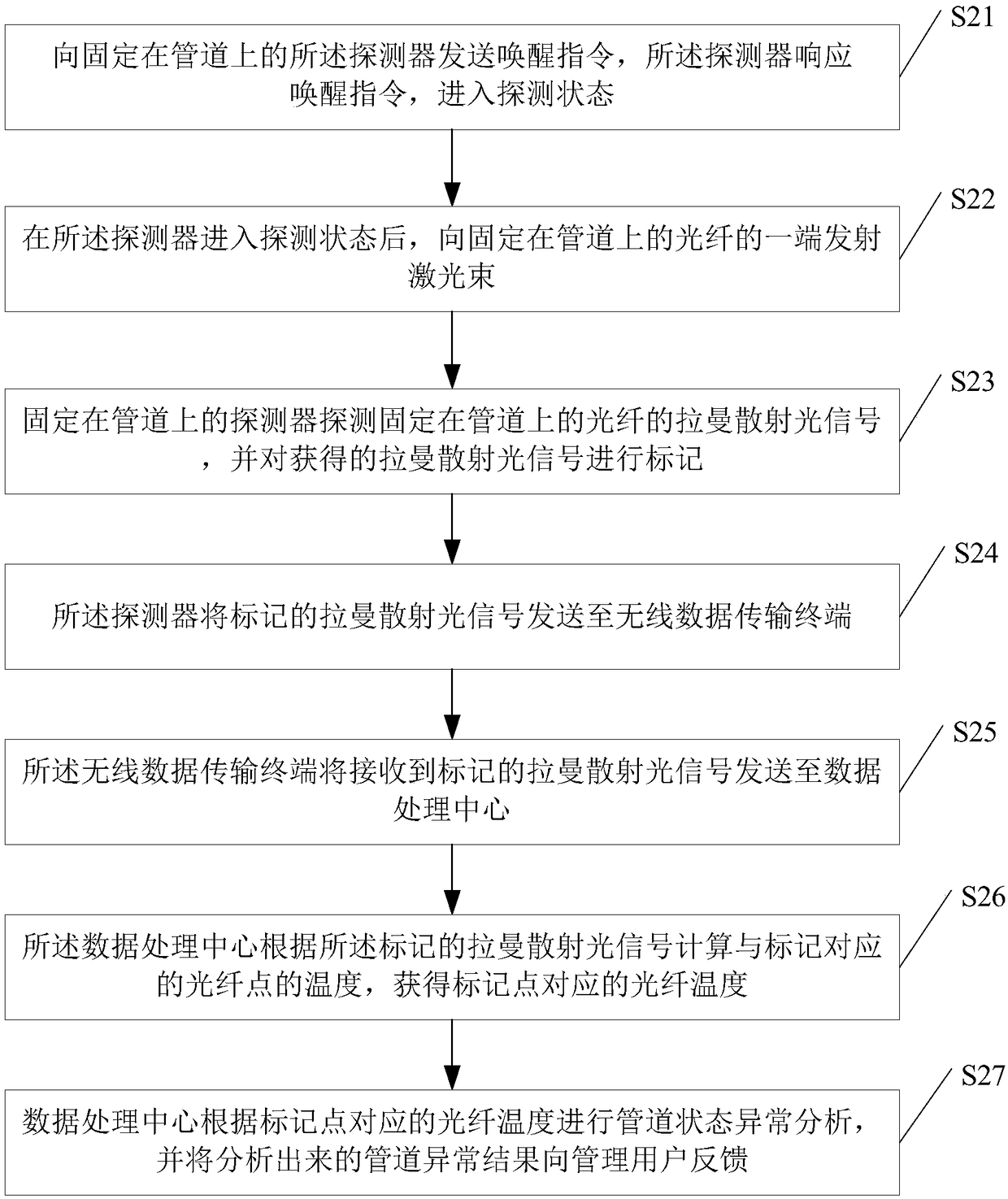
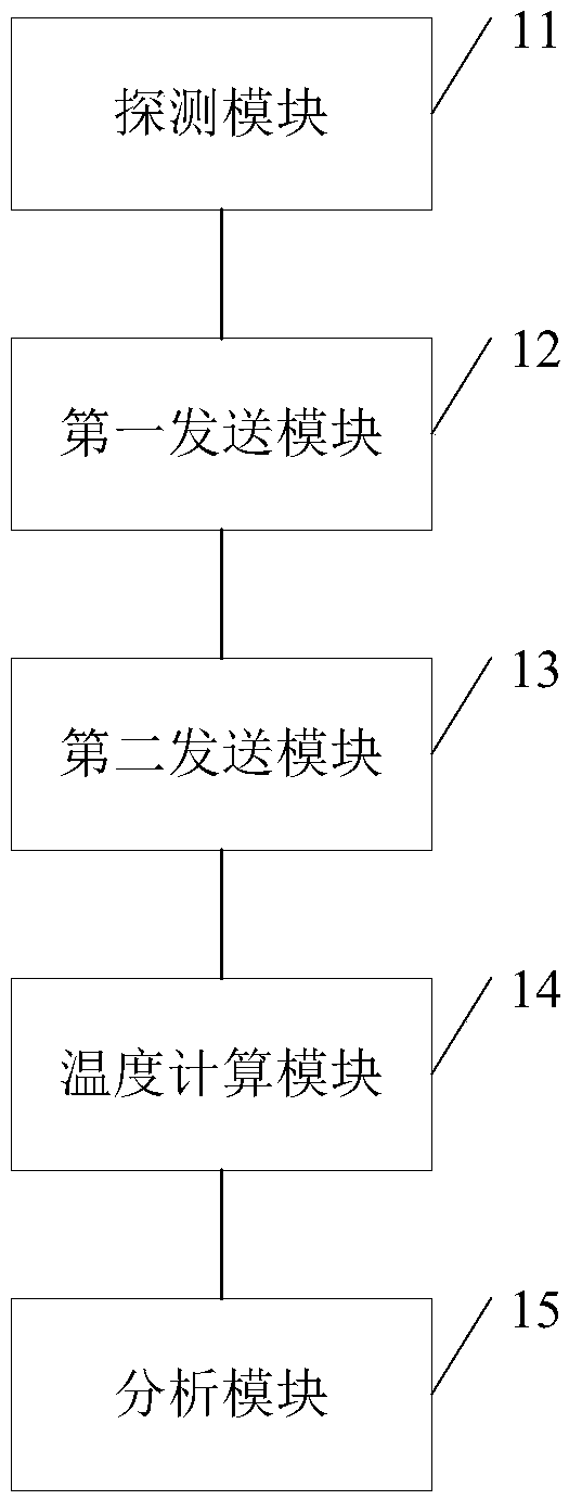

Image

  • Pipeline anomaly prediction method and device based on optical fiber Raman scattering light
  • Pipeline anomaly prediction method and device based on optical fiber Raman scattering light
  • Pipeline anomaly prediction method and device based on optical fiber Raman scattering light

Examples


Embodiment

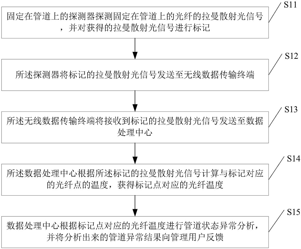
[0048] see figure 1 , figure 1 It is a schematic flow chart of the pipeline abnormality prediction method based on optical fiber Raman scattered light in the embodiment of the present invention.

[0049] Such as figure 1 As shown, a pipeline anomaly prediction method based on optical fiber Raman scattered light, the method includes:

[0050] S11: the detector fixed on the pipeline detects the Raman scattered light signal of the optical fiber fixed on the pipeline, and marks the obtained Raman scattered light signal;

[0051] In the specific implementation process, an optical fiber is embedded in the pipeline wall, or an optical fiber is arranged along the pipeline wall, and detectors are arranged on the optical fiber at equal or unequal intervals, wherein the detector is used to detect the A detector for Raman scattered light signals; the detector is installed on the optical fiber to detect the Raman scattered light signal on the optical fiber; the distance between the dete...


PUM


Abstract

The invention discloses a pipeline anomaly prediction method and device based on optical fiber Raman scattering light. The pipeline anomaly prediction method comprises the steps that a detector fixedto a pipeline detects a Raman scattering light signal of an optical fiber fixed to the pipeline, and the obtained Raman scattering light signal is marked; the detector sends the marked Raman scattering light signal to a wireless data transmission terminal; the wireless data transmission terminal sends the received marked Raman scattering light signal to a data processing center; the data processing center calculates the temperature of an optical fiber point corresponding to a mark according to the marked Raman scattering light signal, and thus the temperature of the optical fiber correspondingto a mark point is obtained; and the data processing center conducts pipeline state anomaly analysis according to the temperature of the optical fiber corresponding to the mark point and feeds an analyzed pipeline anomaly result back to a management user. According to the pipeline anomaly prediction method and device based on the optical fiber Raman scattering light, the signal is collected on the pipeline wall, the collected signal is uploaded to the data center to be analyzed, pipeline anomaly prediction is conducted, and the pipeline deeply buried under the ground is managed conveniently.

Description

technical field [0001] The invention relates to the technical field of pipeline anomaly detection, in particular to a pipeline anomaly prediction method and device based on optical fiber Raman scattered light. Background technique [0002] Today, with the rapid development of urbanization, there are more and more ground buildings and underground facilities are becoming more and more dense. The number and scale of urban underground pipelines are increasing, and their composition is becoming more and more complex. What exactly is the underground pipeline? At present, I am afraid that no city can fully explain it. The burying process of underground pipelines is diversified, the burying time is different, and the purposes of pipelines are also different. The parameters of the underground medium in the place where the pipeline is buried are not uniform and changeable. The scale of the urban underground pipe network is still expanding. However, due to the long laying time, a la...

Claims


Application Information

Patent Timeline
Patent Type & Authority Applications(China)
IPC IPC(8): G01K11/32G01K11/324
CPCG01K11/32G01K11/324
Inventor 汤铁卉
Owner 广东聚源管业实业有限公司
Learn More