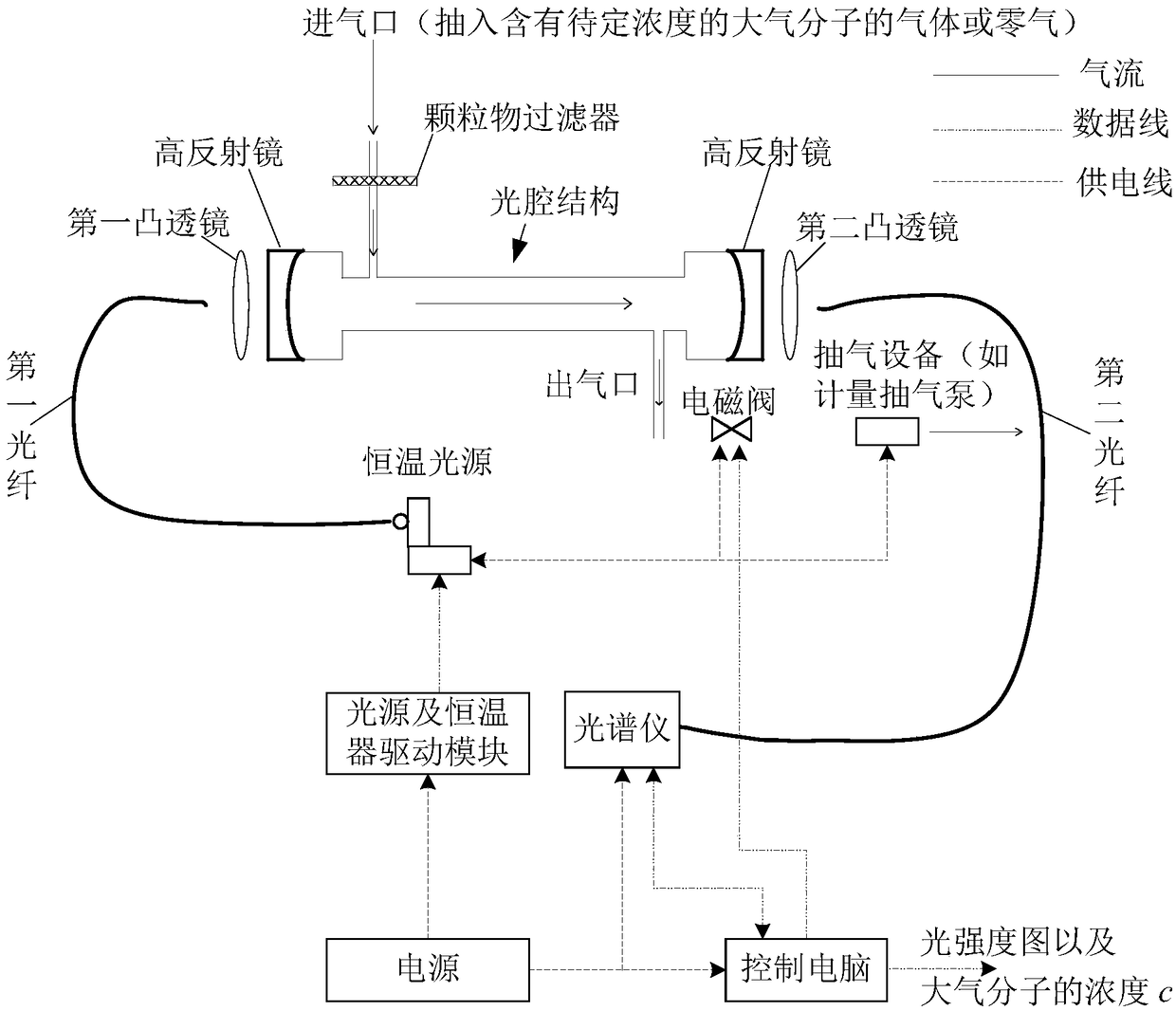
Sweeping gas path device applied to optical cavity structure

A technology of purging gas path and purging gas, which is applied in the direction of measuring device, color/spectral characteristic measurement, material analysis through optical means, etc. It can solve the problems of unsatisfactory detection effect, cumbersome, added complexity and steps, etc.

Inactive Publication Date: 2019-01-11
深圳市卡普瑞环境科技有限公司
View PDF7 Cites 2 Cited by
  • Summary
  • Abstract
  • Description
  • Claims
  • Application Information

AI Technical Summary

Problems solved by technology

In the prior art, before using a detection instrument to detect the concentration of atmospheric molecules, it is usually necessary to calibrate the sensitivity coefficient (sensitivity coefficient) of the detection instrument with a standard gas of known concentration, and to calibrate the detection with a standard gas of known concentration. The sensitivity factor of the instrument will add additional complexity and steps to the detection; in addition, the purchase and transportation of standard gases may be expensive, cumbersome, and sometimes difficult to obtain standard gases (such as N 2 o 5 and NO 3 ), thereby exacerbating the difficulty of detection; in addition, the existing detection instruments are not ideal for the detection of ultra-low concentrations of atmospheric molecules

Method used


Image

  • Sweeping gas path device applied to optical cavity structure
  • Sweeping gas path device applied to optical cavity structure
  • Sweeping gas path device applied to optical cavity structure

Examples


Embodiment Construction

[0039] The technical solutions in the embodiments of the present application will be clearly and completely described below in conjunction with the drawings in the embodiments of the present application. Apparently, the described embodiments are only some of the embodiments of the present application, rather than all the embodiments. Based on the embodiments in this application, all other embodiments obtained by persons of ordinary skill in the art without making creative efforts belong to the scope of protection of this application.

[0040] It should be noted that the terms "comprising" and "having" and any variations thereof in the embodiments of the present application are intended to cover non-exclusive inclusion, for example, a process, method, system, product, or process that includes a series of steps or units. The apparatus is not necessarily limited to those steps or units explicitly listed, but may include other steps or units not explicitly listed or inherent to th...


PUM


Abstract

The invention provides a sweeping gas path device applied to an optical cavity structure. The sweeping gas path device can be used for respectively guiding sweeping gas (such as high-purity nitrogen or air) in front of high reflective mirrors at two ends of the optical cavity structure, so that the gas containing atmospheric molecules having undetermined concentration inside the optical cavity structure is blocked to directly contact the surfaces of the high reflective mirrors at two ends of the optical cavity structure, reflectivity reduction of the mirror surfaces caused by gas or particle adsorption can be avoided. Based on the device, the optical cavity structure can be used for detecting the concentration of atmospheric molecules by directly detecting optical absorption of atmosphericmolecules, the sensitivity coefficient of detection instrument is not required to be calibrated with standard gas having known concentration, and the concentration of atmospheric molecules and extinction of atmospheric particles can be effectively and conveniently detected. Furthermore, a light is reflected back and forth for multiple times between the two high reflective mirrors to remarkably increase the absorption optical path, absorption of atmospheric molecules can be remarkably increased, and the concentration of atmospheric molecules having ultralow concentration can be effectively detected.

Description

technical field [0001] The present application relates to the technical field of environmental monitoring, and in particular to a purge gas circuit device applied to an optical cavity structure. Background technique [0002] With the continuous development of society and economy, air pollution has attracted more and more attention in most parts of the world, especially in developing countries. In order to detect the severity of air pollution, it is usually necessary to use detection instruments to analyze atmospheric molecules (such as NO 2 , HCHO, CHOCHO, N 2 o 5 , NO 3 , HONO, etc.) to detect the concentration. In the prior art, before using a detection instrument to detect the concentration of atmospheric molecules, it is usually necessary to calibrate the sensitivity coefficient (sensitivity coefficient) of the detection instrument with a standard gas of known concentration, and to calibrate the detection with a standard gas of known concentration. The sensitivity f...

Claims


Application Information

Patent Timeline
IPC IPC(8): G01N21/15G01N21/03G01N21/31
CPCG01N21/0303G01N21/15G01N21/31G01N2021/151
Inventor 欧阳彬王玉政
Owner 深圳市卡普瑞环境科技有限公司
Why Eureka
Try Eureka