Method and system for detecting glass piece cracks of glass insulators

A technology for glass insulators and glass parts, which is applied in the direction of material analysis, measuring devices, optical testing flaws/defects by optical means, etc., can solve the problems of large size of glass insulators, poor crack detection accuracy, complex scattering characteristics, etc. The effect of production cost, widening application, and improving detection efficiency

Active Publication Date: 2019-01-11
CHINA ELECTRIC POWER RES INST +2
View PDF5 Cites 8 Cited by
  • Summary
  • Abstract
  • Description
  • Claims
  • Application Information

AI Technical Summary

Problems solved by technology

[0004] Glass insulators are large in size and extremely complex in shape. Since the height of each layer of concentric circles is large and the height of each layer is different, the greater the height, the worse the light transmission and the more complex the scattering characteristics. Traditional visual inspection or natural light observation, etc. The detection method will easily cause a certain missed detection rate; if ultrasonic measurement is used, the thread structure will cause multiple reflection signals and scattering signals to overlap, which will seriously affect the judgment of scattering signals caused by cracks and other cracks. It is difficult to detect cracks in the multi-layer thick-walled structure distributed at the bottom and the cylindrical structure area of ​​the threaded head, so the glass insulators in the prior art have the disadvantage of poor crack detection accuracy

Method used


Image

  • Method and system for detecting glass piece cracks of glass insulators
  • Method and system for detecting glass piece cracks of glass insulators

Examples


Embodiment Construction

[0042] Exemplary embodiments of the present invention will now be described with reference to the drawings; however, the present invention may be embodied in many different forms and are not limited to the embodiments described herein, which are provided for the purpose of exhaustively and completely disclosing the present invention. invention and fully convey the scope of the invention to those skilled in the art. The terms used in the exemplary embodiments shown in the drawings do not limit the present invention. In the figures, the same units / elements are given the same reference numerals.

[0043] Unless otherwise specified, the terms (including scientific and technical terms) used herein have the commonly understood meanings to those skilled in the art. In addition, it can be understood that terms defined by commonly used dictionaries should be understood to have consistent meanings in the context of their related fields, and should not be understood as idealized or over...


PUM


Abstract

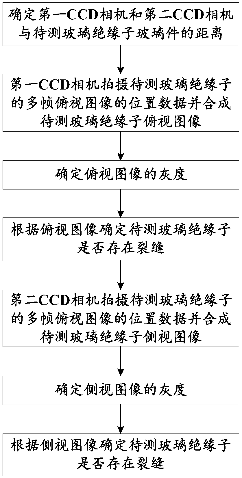
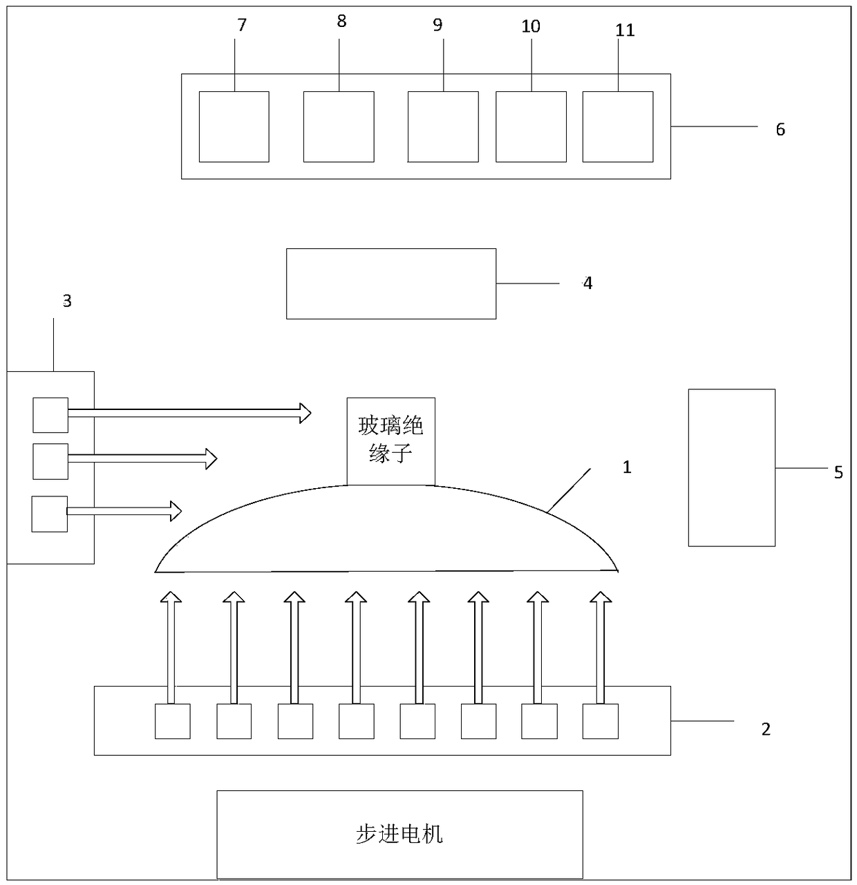
The invention discloses a method and system for detecting glass piece cracks of glass insulators and belongs to the technical field of power equipment maintenance. The method disclosed by the invention comprises the following steps: determining the distance between a CCD (Charge Coupled Device) camera and glass pieces of to-be-detected glass insulators; shooting position data of multi-frame overlook images of the to-be-detected glass insulators by a first CCD camera, synthesizing overlook images of the to-be-detected glass insulators, and determining the gray level of the overlook images; determining whether the to-be-detected glass insulators have cracks according to the overlook images; shooting position data of multi-frame overlook images of the to-be-detected glass insulators by a second CCD camera, synthesizing side-looking images of the to-be-detected glass insulators, and determining the gray level of the side-looking images; determining whether the to-be-detected glass insulators have cracks according to the side-looking images; calculating the sizes and positions of the cracks if the cracks exist, and submitting the sizes and positions of the cracks to a database; and determining that the to-be-detected glass insulators are qualified when the cracks do not exist. According to the method and system disclosed by the invention, the crack detection accuracy is obviously improved by virtue of all-round light source distribution and image acquisition.

Description

technical field [0001] The invention belongs to the technical field of electric equipment maintenance, and more specifically relates to a method and system for detecting cracks in glass parts of glass insulators. Background technique [0002] As a traditional line material, glass disc suspension insulators are widely used in transmission lines of various voltage levels. In addition to the excellent insulation performance of glass insulators, its main purpose is that the tempered layer will be damaged when the insulating parts of the glass insulator are damaged or aged, causing internal stress to collapse, which will cause the glass parts to self-explode. Currently, glass insulators are allowed in the technical specifications. A certain self-explosion ratio is no more than 0.02% / year for conventional lines and no more than 0.01% / year for UHV lines. However, in some lines, glass insulators will self-explode in a large area. This kind of self-explosion may occur before or afte...

Claims


Application Information

Patent Timeline
Patent Type & Authority Applications(China)
IPC IPC(8): G01N21/88
CPCG01N21/8806G01N21/8851G01N2201/06146G01N2201/06113G01N2021/888G01N2021/8887G01N2021/8874
Inventor 袁田李政言刘翔张锐付超代静汪英英闫力松武文华蔡勇江山王昱晴张虎张勤郭靖夏旭东范建二沈亚梅孔俊飞
Owner CHINA ELECTRIC POWER RES INST
Why Eureka
Try Eureka