A liquid conductivity detection system
A detection system and conductivity technology, applied in the direction of fluid resistance measurement, components of electrical measurement instruments, measurement of electricity, etc., can solve the problems of increased application cost, inability to meet requirements, and expensive chips, to simplify the detection process, reduce The effect of hardware cost
- Summary
- Abstract
- Description
- Claims
- Application Information
AI Technical Summary
Problems solved by technology
Method used
Image
Examples
Embodiment 2
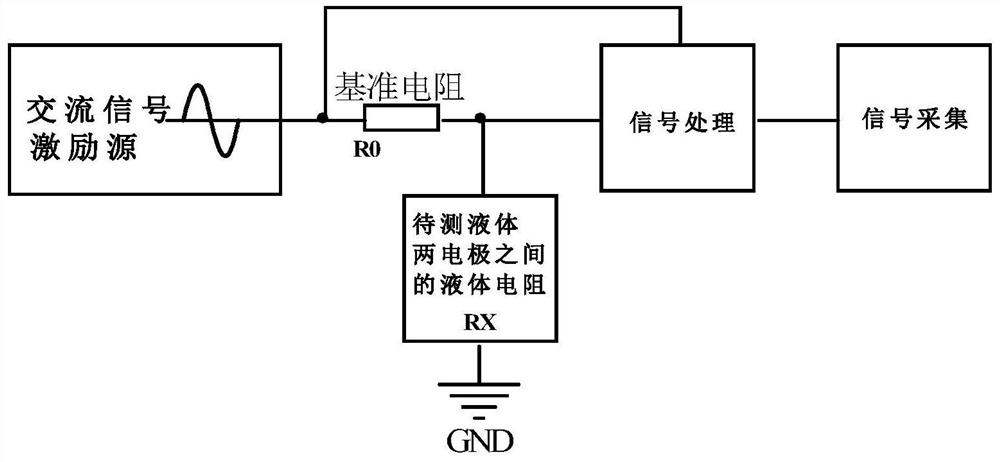
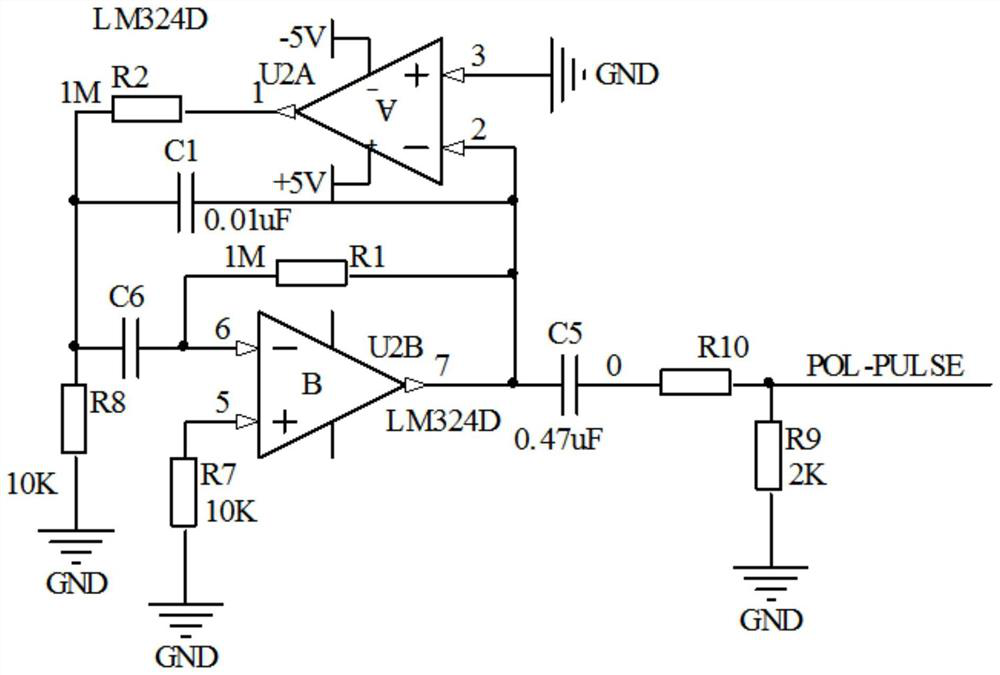
[0019] Embodiment 2: On the basis of Embodiment 1, the AC signal excitation source of this design is as follows figure 2 As shown, including operational amplifier U2A and operational amplifier U2B, pin 3 of operational amplifier U2A is grounded, pin 2 of operational amplifier U2A is connected to resistor R1, capacitor C1, capacitor C5 and pin 7 of operational amplifier U2B, and the other end of capacitor C5 is connected to resistor R10, the other end of resistor R10 is connected to excitation source signal POL-PULSE and resistor R9, pin 1 of operational amplifier U2A is connected to resistor R2, the other end of resistor R2 is connected to capacitor C1, capacitor C6 and resistor R8, and the other end of capacitor C6 is connected to resistor The other end of R1 is connected to the pin 6 of the operational amplifier U2B, and the pin 5 of the operational amplifier U2B is grounded through the resistor R7. In this circuit, an operational amplifier chip LM324 is used to generate a ...
Embodiment 3
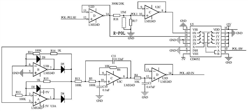
[0020] Embodiment 3, on the basis of embodiment 2, the signal processing circuit of this design is as image 3 As shown, it includes the operational amplifier U2D and the chip U5, the pin 12 of the operational amplifier U2D is connected to the excitation source signal POL-PULSE, the pin 13 of the operational amplifier U2D is connected to the pin 14 of the chip U5, the pin 14 of the operational amplifier U2D and the resistor R18, and the resistor R18 The other end of the resistor R17 is connected to the pin 10 of the operational amplifier U2C, the pin 8 of the operational amplifier U2C is connected to the pin 9 of the operational amplifier U2C and the pin 12 of the chip U5, the pin 13 of the chip U5 is connected to the pin 3 of the operational amplifier U3A, and the operational amplifier U3A Pin 2 of pin 2 is connected to the anode of diode D2, resistor R15 and resistor R12, the other end of resistor R12 is connected to resistor R11, the anode of diode D3, the other end of resis...
Embodiment 4
[0022] Embodiment 4, on the basis of embodiment 3, the signal acquisition circuit of this design is as Figure 4 As shown in the figure, ADS1100 is a 16-bit single-channel AD converter, and ADS-VREF is a 5V reference voltage. After POL-AD-IN is sampled by AD, it is read into the CPU by ADS-SDA and ADS-SCL serial interfaces. Signal Acquisition.
PUM
 Abstract
Description
Claims
Application Information
 - R&D
- Intellectual Property
- Life Sciences
- Materials
- Tech Scout
- Unparalleled Data Quality
- Higher Quality Content
- 60% Fewer Hallucinations
Browse by: Latest US Patents, China's latest patents, Technical Efficacy Thesaurus, Application Domain, Technology Topic, Popular Technical Reports.
© 2025 PatSnap. All rights reserved.Legal|Privacy policy|Modern Slavery Act Transparency Statement|Sitemap|About US| Contact US: help@patsnap.com


