Calibration method and device for measuring electrical characteristics of microwave semiconductor integrated circuits

A technology for calibrating devices and integrated circuits, which is applied in the directions of measuring devices, electronic circuit testing, measuring electricity, etc., can solve the problems of low efficiency, limited measurement accuracy, single function, etc., and achieves high efficiency, simple calibration method, and versatility. strong effect

Active Publication Date: 2020-11-03
CHINA ELECTRONIS TECH INSTR CO LTD +1
View PDF8 Cites 0 Cited by
  • Summary
  • Abstract
  • Description
  • Claims
  • Application Information

AI Technical Summary

Problems solved by technology

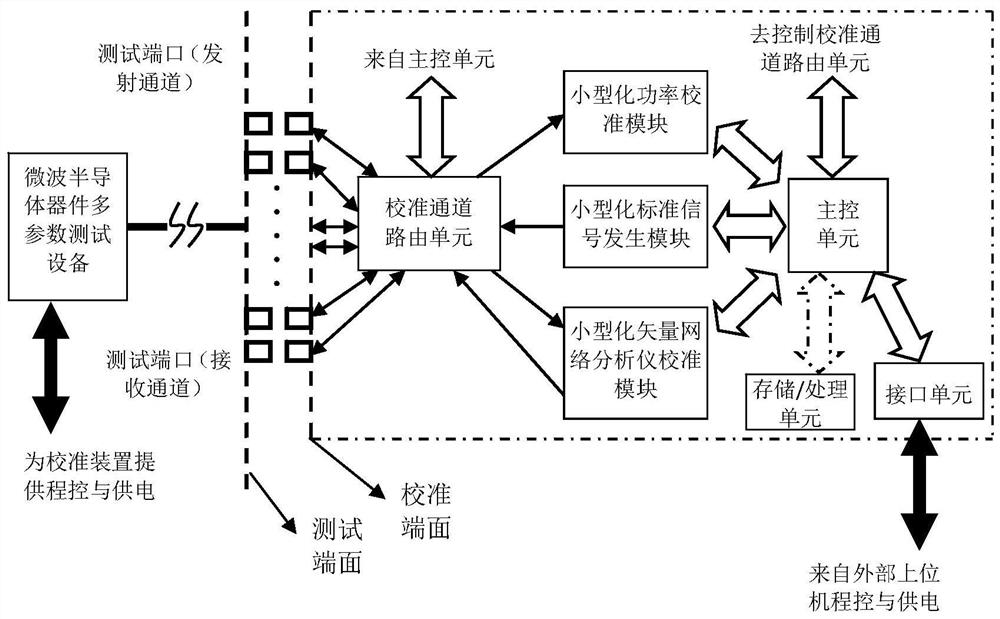
[0008] In order to solve the deficiencies of the prior art, the present disclosure provides a calibration method and device for measuring the electrical characteristics of microwave semiconductor integrated circuits, through which the efficient integrated measurement and control of multi-parameter test equipment and calibration devices for microwave semiconductor devices can be realized Work, complete the automatic identification and call processing of equipment working status and calibration data, complete the output signal power and scattering parameter calibration of multiple transceiver channels at one time, and realize and provide high-accuracy measurement capability characteristics on the corresponding calibration surface. Support the generalization of relevant electrical characteristics within the scope of measurement and provide efficient and accurate measurement solutions to effectively solve the problems of low efficiency, single function and measurement based on traditional calibration methods that are difficult to unify the calibration surface and the test surface on the same end surface. Accuracy is limited, etc.

Method used


Image

  • Calibration method and device for measuring electrical characteristics of microwave semiconductor integrated circuits
  • Calibration method and device for measuring electrical characteristics of microwave semiconductor integrated circuits

Examples


Embodiment Construction

[0033] The present disclosure will be further described below in conjunction with the accompanying drawings and specific embodiments.

[0034] It should be pointed out that the following detailed description is exemplary and intended to provide further explanation to the present application. Unless defined otherwise, all technical and scientific terms used herein have the same meaning as commonly understood by one of ordinary skill in the art to which this application belongs.

[0035] It should be noted that the terminology used here is only for describing specific implementations, and is not intended to limit the exemplary implementations according to the present application. As used herein, unless the context clearly dictates otherwise, the singular is intended to include the plural, and it should also be understood that when the terms "comprising" and / or "comprising" are used in this specification, they mean There are features, steps, operations, means, components and / or ...


PUM


Abstract

The invention provides a calibration device for measuring electrical characteristics of a microwave semiconductor integrated circuit. The calibration device comprises a main control unit, microwave semiconductor device multi-parameter test equipment, a calibration channel routing unit, a power calibration module, a standard signal generation module and a vector network analyzer calibration module,wherein the main control unit is configured to receive calibration configuration information and a program control command from the microwave semiconductor device multi-parameter test equipment through external program control and power supply functions; the calibration channel routing unit is used for constructing corresponding output signal power calibration channel, signal receiving characteristic calibration channel and scattering parameter test characteristic calibration channel for test ports respectively; and the power calibration module, the standard signal generation module and the vector network analyzer calculation module are configured to perform automatic calibration of corresponding parameter characteristic tests in a single connection mode.

Description

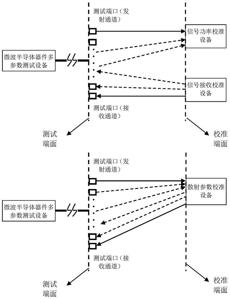
technical field [0001] The disclosure belongs to the technical field of microwave testing, and in particular relates to a calibration method and device for measuring electrical characteristics of microwave semiconductor integrated circuits. Background technique [0002] With the industrialization of microwave semiconductor integrated circuits, the requirements for the measurement efficiency and accuracy of the electrical characteristics of microwave semiconductor integrated circuits are getting higher and higher. [0003] The schematic diagram of the traditional calibration method for the measurement of the electrical characteristics of microwave semiconductor integrated circuits is as follows: figure 1 shown. to combine figure 1 As well as the demand analysis of practical applications, it can be seen that the traditional calibration method for measuring the electrical characteristics of microwave semiconductor integrated circuits has the following shortcomings: [0004] ...

Claims


Application Information

Patent Timeline
Patent Type & Authority Patents(China)
IPC IPC(8): G01R31/28G01R35/00
CPCG01R31/2851G01R35/005
Inventor 郭敏丁志钊王尊峰朱学波徐宝令
Owner CHINA ELECTRONIS TECH INSTR CO LTD
Why Eureka
Try Eureka