
Ionospheric scintillation monitoring system for large amplitude ionospheric scintillation

A monitoring system and ionosphere technology, applied in radio wave measurement system, satellite radio beacon positioning system, measurement device, etc., can solve the problems of poor normal reception of GNSS signals, inability to monitor large-scale ionospheric scintillation, etc., to achieve Monitor, extend the effect of the relevant integration time

Active Publication Date: 2019-01-11
ACAD OF OPTO ELECTRONICS CHINESE ACAD OF SCI
View PDF5 Cites 5 Cited by
  • Summary
  • Abstract
  • Description
  • Claims
  • Application Information

AI Technical Summary

Problems solved by technology

If it is not affected by any interference, the signal power of the GNSS signal reaching the ground surface is about -160dBW, and the signal is very weak, while the conventional GNSS signal receiving method usually only has a margin of about 10dB for weak signals, that is, when the signal power When it drops below about -170dBW, the normal reception of GNSS signals will be severely degraded
The weakening of ionospheric scintillation to GNSS signals can reach more than 30dB at most. Therefore, the ionospheric scintillation monitoring technology using the conventional GNSS signal receiving method can only monitor small-scale ionospheric scintillation, and cannot monitor large-scale ionospheric scintillation.

Method used


Image

  • Ionospheric scintillation monitoring system for large amplitude ionospheric scintillation
  • Ionospheric scintillation monitoring system for large amplitude ionospheric scintillation
  • Ionospheric scintillation monitoring system for large amplitude ionospheric scintillation

Examples


Embodiment Construction

[0062] In order to enable those skilled in the art to better understand the solutions of the present application, the technical solutions in the embodiments of the present application will be clearly and completely described below in conjunction with the drawings in the embodiments of the present application.

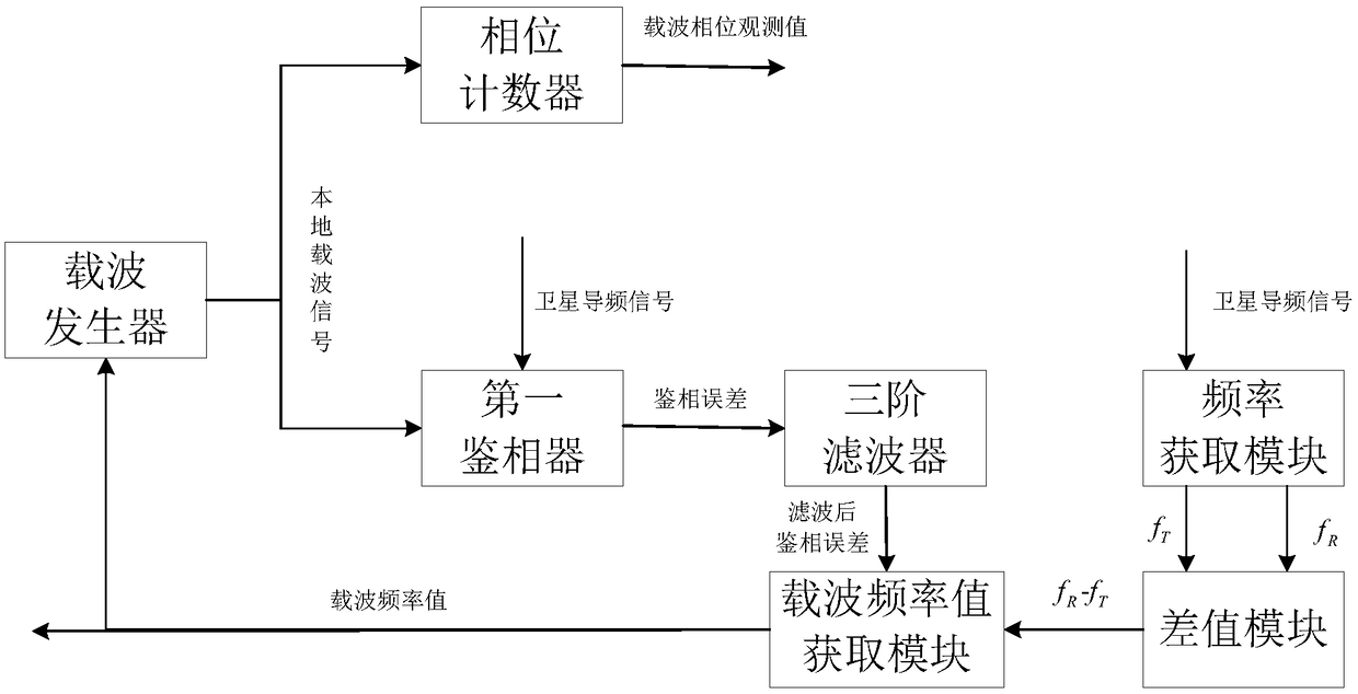
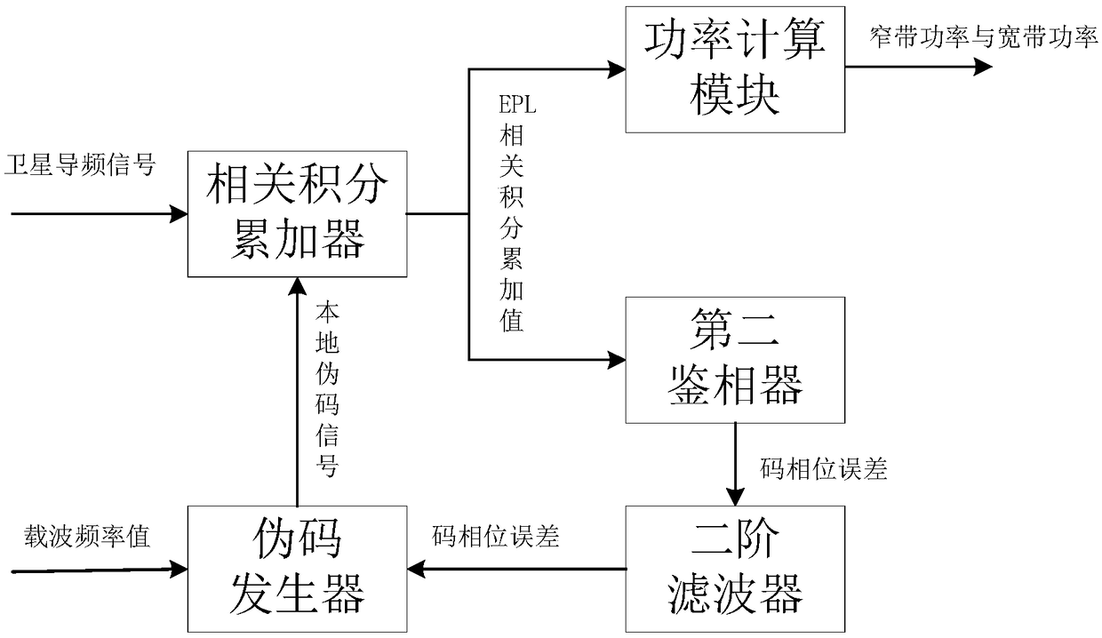
[0063] see figure 1 , which is a functional block diagram of an ionospheric scintillation monitoring system for large-amplitude ionospheric scintillation provided by this embodiment. An ionospheric scintillation monitoring system for large-amplitude ionospheric scintillation, including an antenna, a carrier tracking loop, a code tracking loop, and a processing module;

[0064] The antenna is used to receive satellite pilot signals in real time;

[0065] The carrier tracking loop is used to receive and track the satellite pilot signal, thereby obtaining the carrier phase observation value φ and the carrier frequency value f of the satellite pilot signal carrier ;

[0...


PUM


Abstract

The invention provides an ionospheric scintillation monitoring system for large amplitude ionospheric scintillation. The invention combines a carrier tracking loop and a code tracking loop, and extends the correlation integral time of the whole system, therefore can track continuously the GNSS signal severely attenuated due to the large amplitude ionospheric scintillation, and can monitor the large amplitude ionospheric scintillation.

Description

technical field [0001] The invention belongs to the application fields of space weather monitoring and satellite navigation, and in particular relates to an ionospheric scintillation monitoring system for large-amplitude ionospheric scintillation. Background technique [0002] Global Navigation Satellite System (GNSS), as an important infrastructure for countries in the information age, can provide more accurate positioning, navigation, and timing services on a global scale, and can also be used for ionospheric monitoring in space weather monitoring. scintillation monitoring applications, and using GNSS signals as beacons for ionospheric scintillation monitoring is an inexpensive means of monitoring. [0003] Ionospheric scintillation will weaken the GNSS signal power, and the ionospheric amplitude scintillation index and ionospheric phase scintillation index can be estimated after the GNSS signal that passes through the ionosphere and reaches the earth's surface is received...

Claims


Application Information

Patent Timeline
Patent Type & Authority Applications(China)
IPC IPC(8): G01S19/29
CPCG01S19/29Y02A90/10
Inventor 袁超袁洪李子申徐颖田向伟史雨薇
Owner ACAD OF OPTO ELECTRONICS CHINESE ACAD OF SCI
Learn More