Self-powered maintenance device and method for photoelectric equipment

A technology for maintenance and equipment, which is applied in general control systems, instruments, computer control, etc., can solve problems such as many manual steps involved, battery overcharge damage, high laser pulse trigger frequency damage equipment, etc., to improve the efficiency of power-on maintenance , reasonable design and simplified manual operation steps

Active Publication Date: 2019-01-11
ARMY ENG UNIV OF PLA
View PDF5 Cites 0 Cited by
  • Summary
  • Abstract
  • Description
  • Claims
  • Application Information

AI Technical Summary

Problems solved by technology

[0003] One of the purposes of the present invention is to provide an autonomous power-on maintenance device for photoelectric equipment to solve a series of problems such as many manual steps involved in the whole process of power-on maintenance, battery overcharge damage, and laser pulse trigger frequency that is too high to damage equipment.

Method used


Image

  • Self-powered maintenance device and method for photoelectric equipment
  • Self-powered maintenance device and method for photoelectric equipment
  • Self-powered maintenance device and method for photoelectric equipment

Examples


Embodiment Construction

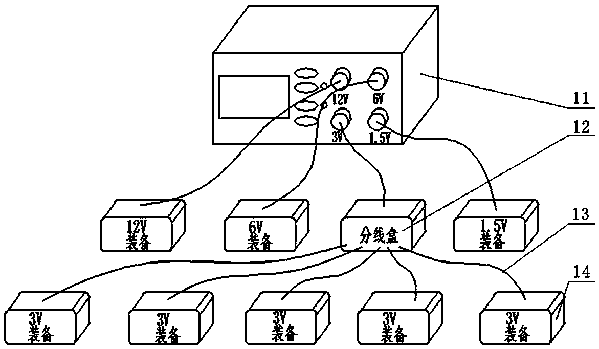
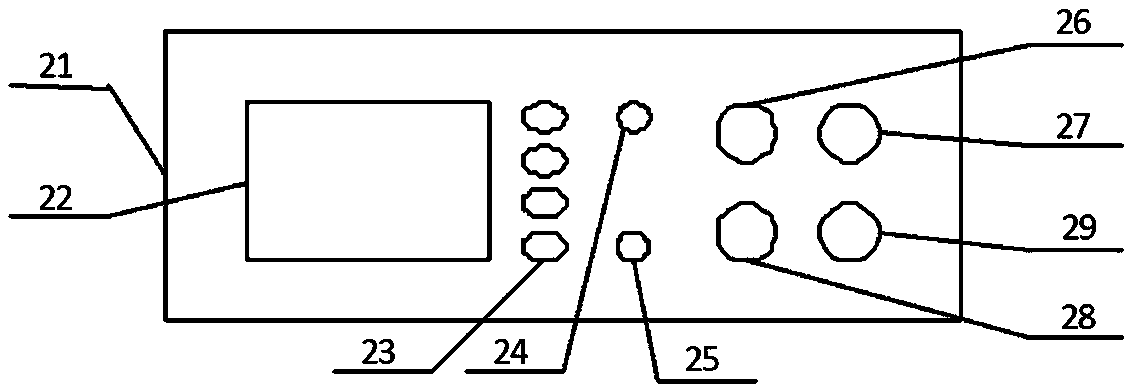
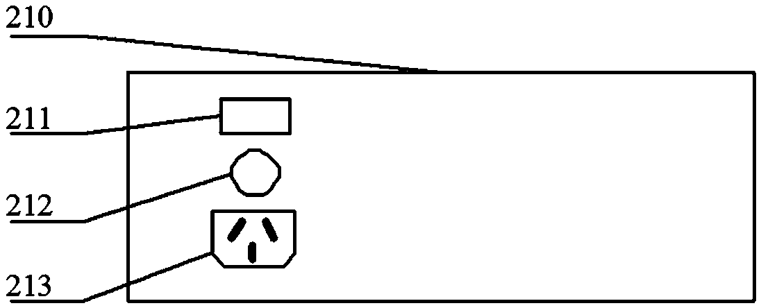
[0039] Such as figure 1 As shown, the self-powered maintenance device for optoelectronic equipment provided by the present invention includes a host 11 (or called the main unit of the self-powered maintenance device), a junction box 12 and supporting cables 13 . The main frame 11 is a cuboid box body structure, and it comprises a case shell, and a front control panel 21 (such as figure 2 shown), a rear control panel 210 is provided on the rear panel of the chassis shell (such as image 3 shown), with a circuit board inside the chassis shell. The host 11 can output 1.5V, 3V, 6V, 12V multi-level DC voltage at the same time, cooperate with the junction box 12 to expand the interface, and can support multiple types of equipment for simultaneous maintenance, which greatly improves the efficiency of power-on maintenance. The voltage output by the host 11 can be directly connected to the optoelectronic equipment, or can be connected to the optoelectronic equipment 14 after going t...


PUM


Abstract

The invention provides a self-powered maintenance device and method for photoelectric equipment. The self-powered maintenance device comprises a main machine, an adapter junction box and matched cables. The main machine converts the alternating voltage into multi-level direct voltage to output through a voltage conversion module and achieves self-powered maintenance through a control circuit. Theadapter junction box separates a single output interface into a plurality of output interfaces in parallel connection to achieve simultaneous self-powered maintenance for a plurality of photoelectricequipment. The matched cables are used for being connected with the main machine and the photoelectric equipment with different types. The self-powered maintenance device can realize the self-poweredmaintenance of the photoelectric equipment without people on duty. Power-on maintenance steps are simplified, power-on maintenance efficiency is improved, the problems of photoelectric equipment battery overcharge damage and excessive laser pulse trigger frequency damaging equipment are solved. The device can also be used as an emergency external power supply for various types of the photoelectricequipment.

Description

technical field [0001] The invention relates to a photoelectric equipment maintenance device, in particular to a photoelectric equipment self-powered maintenance device and method. Background technique [0002] In order to maintain the good technical status of military optoelectronic equipment such as low-light night vision, infrared thermal imaging, TV reconnaissance and laser range finder, and prolong the service life, regular power-on maintenance is an important measure. In the army's equipment warehouses, equipment manufacturers and equipment users, due to the variety and quantity of optoelectronic equipment, power-on maintenance is a time-consuming and complicated task. The current power-on maintenance method is: first charge the batteries of various types of equipment, then put the charged batteries into the battery compartment of the photoelectric equipment, turn on the power switch of the equipment, let the instrument be in working condition, and manually time the po...

Claims


Application Information

Patent Timeline
Patent Type & Authority Applications(China)
IPC IPC(8): G05B19/042
CPCG05B19/0428G05B2219/24024
Inventor 应家驹周冰黄富瑜陈玉丹武东生刘杰王元铂殷建玲
Owner ARMY ENG UNIV OF PLA
Why Eureka
Try Eureka