A method of electrolytic plating power supply

An electrolytic electroplating and power supply technology, applied in the modification of power electronics, electrical components, and output power conversion devices, etc., can solve the problems of damage to the power supply group, affecting the quality of electroplating, failure to achieve anti-corrosion, etc., and achieve stable internal current. Convenient control and detection to ensure the effect of normal operation

Active Publication Date: 2020-04-28
双新电器(郑州)制造有限公司
View PDF9 Cites 0 Cited by
  • Summary
  • Abstract
  • Description
  • Claims
  • Application Information

AI Technical Summary

Problems solved by technology

[0002] In the electroplating industry, since the power supply cannot be disconnected from the beginning of the electroplating until the end of the electroplating, the electroplating equipment has high requirements for the continuity of the power supply. However, the existing electroplating equipment power supply generally adopts the structure of a single power supply device However, when the power supply device breaks down, the power supply of the electroplating equipment will stop immediately, causing the electroplating raw materials and products in the electroplating pool to be scrapped. However, if the pure power supply is connected in parallel, when one of the power supply modules fails, the current of other power supply modules will rebound, which will not only cause damage to the power supply group, but also affect the normal power supply of the power supply group. The current in the electroplating equipment is unstable, which seriously affects the quality of electroplating
[0003] Parallel connection of power modules needs to set up a main power module with a built-in monitoring device. When the main power fails, the power group will be paralyzed. Therefore, the traditional electroplating power supply is no longer suitable for the existing production and use requirements, because there are some problems. First, Faults will occur in a chain reaction. One fault will affect the entire device. Second, during the electroplating process, the requirements for the power supply are very high, and the power supply must maintain continuity. Third, the requirements for the sealing and anti-corrosion performance of the power supply are very strict. However, the traditional electroplating power supply has poor sealing performance and cannot achieve the purpose of anti-corrosion. The life of the power supply is short and the stability is poor.

Method used


Image

  • A method of electrolytic plating power supply
  • A method of electrolytic plating power supply
  • A method of electrolytic plating power supply

Examples


Embodiment Construction

[0025] The following will clearly and completely describe the technical solutions in the embodiments of the present invention with reference to the accompanying drawings in the embodiments of the present invention. Obviously, the described embodiments are only some, not all, embodiments of the present invention. Based on the embodiments of the present invention, all other embodiments obtained by persons of ordinary skill in the art without making creative efforts belong to the protection scope of the present invention.

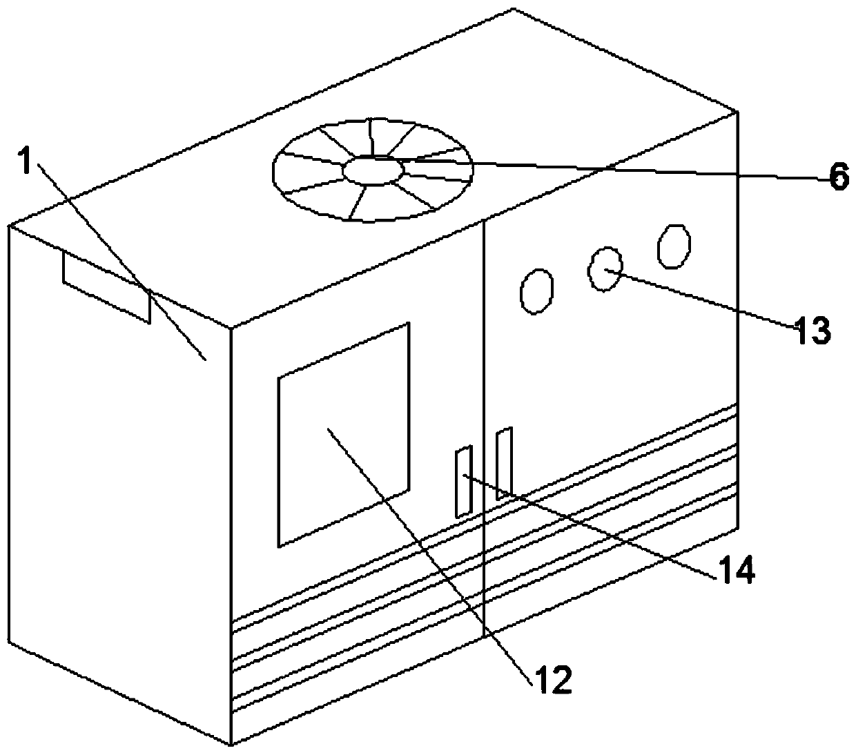
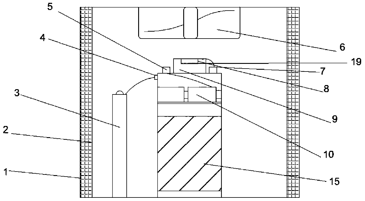
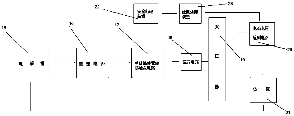
[0026] see Figure 1~3, a method for electrolytic plating power supply, comprising a main box 1, a coolant 2, an information processor 3, a signal switch 4, a current detection port 5, a cooling fan 6, a voltage detection port 7, a voltage regulator 8, an output port 9. Current regulation component 10, ventilation heat sink 11, electronic touch screen 12, safety signal light 13, insulating handle 14, electrolytic tank 15, rectifier circuit 16, unijunction tran...


PUM


Abstract

The invention discloses a method of an electrolytic plating power supply, including a main box, a coolant, an information processor, a signal switch, a current sense port, a heat-dissipating fan, a voltage detection port, a voltage regulator, an output port, current regulate component, ventilation fin, electronic touch display, safety signal lamp, insulated handle, electrolytic cell, rectify circuit, single junction transistor oscillation trigger circuit, inverter circuit, transformer, current voltage detection circuit, load, safety power-off device and information processing device. The invention has the advantages that: the design of the electrolytic plating power supply is reasonable, the information processor facilitates the sorting and merging of the obtained data and the sending of instructions to various circuit ports, The current detection port facilitates the control and detection of the output current and voltage, the current regulating module keeps the internal current stable, and the safety signal lamp facilitates the early warning of the user and the real-time expression of the internal running state.

Description

technical field [0001] The invention relates to a power supply device, in particular to a method for electrolytic plating power supply, which belongs to the technical field of electroplating power supply. Background technique [0002] In the electroplating industry, since the power supply cannot be disconnected from the beginning of the electroplating until the end of the electroplating, the electroplating equipment has high requirements for the continuity of the power supply. However, the existing electroplating equipment power supply generally adopts the structure of a single power supply device However, when the power supply device breaks down, the power supply of the electroplating equipment will stop immediately, causing the electroplating raw materials and products in the electroplating pool to be scrapped. However, if the pure power supply is connected in parallel, when one of the power supply modules fails, the current of other power supply modules will rebound, whic...

Claims


Application Information

Patent Timeline
Patent Type & Authority Patents(China)
IPC IPC(8): H02M1/00H02M5/458H05K7/20
CPCH02M1/00H02M5/458H05K7/20909
Inventor 宋万生耿同明
Owner 双新电器(郑州)制造有限公司
Why Eureka
Try Eureka