Display module structure used for front camera and laminating process thereof

A front-facing camera and display module technology, which is applied to telephone structures, telephone communications, electrical components, etc., can solve problems such as the inability to provide display in the area where the camera is located, the high defect rate of the display module, and the refractive index of residual foreign matter. Achieve the effect of realizing full screen display, improving product expressiveness, and improving yield rate

Pending Publication Date: 2019-01-11
厦门三德信科技股份有限公司
View PDF0 Cites 19 Cited by
  • Summary
  • Abstract
  • Description
  • Claims
  • Application Information

AI Technical Summary

Problems solved by technology

[0005] First, traditionally, the camera and the display cannot be overlapped, because the display will block light from entering the camera, and the camera has a certain volume. When the camera and the display are staggered, the camera occupies a certain space, resulting The area where the camera is located cannot provide display, which is also an important reason why there are relatively large black borders on conventional mobile phones;
[0006] Second, there are existing through-holes in the display module that can block the light from entering, that is, the display screen is also provi

Method used


Image

  • Display module structure used for front camera and laminating process thereof

Examples


Embodiment 1

[0042] The bonding process includes the following process steps:

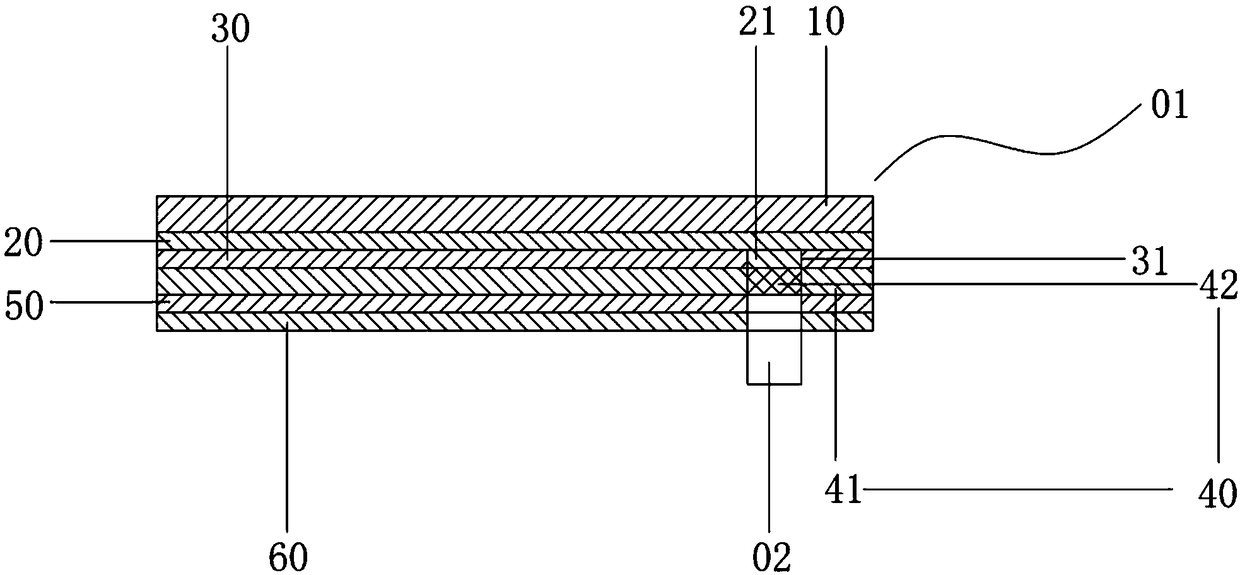
[0043] a. First cut the upper polarizer 30, the lower polarizer 50 and the backlight plate 60 into a size consistent with the shape of the display area 41 of the display screen 40, and remove any pixel grid in the display area 41 on the display screen 40 A non-display area 4142 is formed, and through holes 31 are processed at positions corresponding to the non-display area 4142 of the upper polarizer 30, the lower polarizer 50, and the backlight plate 60;

[0044] b. The OCA optical glue is also cut into a size consistent with the appearance of the display screen 40, and the outer dimension of the glass cover plate 10 is consistent with the appearance of the display screen 40, and then the upper polarizer 30, the OCA optical glue and the glass cover plate 10 are sequentially placed Place it on the display screen 40, place the lower polarizer 50 and the backlight plate 60 under the display screen 40 in sequence,...

Embodiment 2

[0048] The bonding process includes the following process steps:

[0049] a. First cut the upper polarizer 30, the lower polarizer 50 and the backlight plate 60 into a size consistent with the shape of the display area 41 of the display screen 40, and remove any pixel grid in the display area 41 on the display screen 40 A non-display area 4142 is formed, and through holes 31 are processed at positions corresponding to the non-display area 4142 of the upper polarizer 30, the lower polarizer 50, and the backlight plate 60;

[0050] b. The OCA optical glue is also cut into a size consistent with the appearance of the display screen 40, and the outer dimension of the glass cover plate 10 is consistent with the appearance of the display screen 40, and then the upper polarizer 30, the OCA optical glue and the glass cover plate 10 are sequentially placed Place it on the display screen 40, place the lower polarizer 50 and the backlight plate 60 under the display screen 40 in sequence,...

Embodiment 3

[0054] The bonding process includes the following process steps:

[0055] a. First cut the upper polarizer 30, the lower polarizer 50 and the backlight plate 60 into a size consistent with the shape of the display area 41 of the display screen 40, and remove any pixel grid in the display area 41 on the display screen 40 A non-display area 4142 is formed, and through holes 31 are processed at positions corresponding to the non-display area 4142 of the upper polarizer 30, the lower polarizer 50, and the backlight plate 60;

[0056] b. The OCA optical glue is also cut into a size consistent with the appearance of the display screen 40, and the outer dimension of the glass cover plate 10 is consistent with the appearance of the display screen 40, and then the upper polarizer 30, the OCA optical glue and the glass cover plate 10 are sequentially placed Place it on the display screen 40, place the lower polarizer 50 and the backlight plate 60 under the display screen 40 in sequence,...


PUM


Abstract

The present invention provides a display module structure used for a front camera. The structure comprises a display module and a camera module arranged at the lower portion of the display module, thelens of the camera module is arranged facing the direction of the display module, the display module comprises a first optical gluing layer, an upper polaroid, a display screen, a lower polaroid anda back light in order form top to bottom, the display comprises a display area and a non-display area, the camera module is arranged below the non-display area, the upper polaroid is provided with a first light hole corresponding to the non-display area, the lower polaroid is provided with a second light hole corresponding to the non-display area, the back light is provided with a third light holecorresponding to the non-display area, and the first light hole is internally provided with a second optical gluing layer. The present invention further provides a display module laminating process used for a front camera used to display the laminating of the display module.

Description

technical field [0001] The invention relates to the technical field of display modules, in particular to a structure of a display module for a front camera and a bonding process thereof. Background technique [0002] Electronic products, such as smart phones, have occupied the vast majority of the mobile phone market due to their powerful functions. Display screens are an essential human-computer interaction tool for smart phones, and their performance and aesthetics directly affect the actual experience of users. [0003] Due to the advancement of science and technology, the screens of mobile phones are getting bigger and smaller, and the bezels are getting narrower and narrower. The pursuit of full-screen mobile phones with a screen ratio close to 100% has become a mainstream trend in the world. As the screen becomes larger and larger, the handset and sensors of the mobile phone can be made very small and hidden in the frame, but the front camera of the mobile phone is a m...

Claims


Application Information

Patent Timeline
IPC IPC(8): H04M1/02
CPCH04M1/0266H04M1/0264
Inventor 宋刚吴雪和
Owner 厦门三德信科技股份有限公司
Why Eureka
Try Eureka