Cleaner head

A technology for vacuum cleaners and vacuum cleaners, applied in the directions of vacuum cleaners, suction nozzles, cleaning equipment, etc., can solve the problems of high cost and increase the storage space of the head of the cleaner, and achieve the effect of high possibility, improved pickup performance, and good pickup performance.

Inactive Publication Date: 2019-01-11
LUPE TECH LTD
View PDF10 Cites 3 Cited by
  • Summary
  • Abstract
  • Description
  • Claims
  • Application Information

AI Technical Summary

Problems solved by technology

While it may provide good cleaning performance, this is more expensive and requires increased storage space for multiple cleaner heads, and requires additional time and hassle to replace cleaner heads
[0007] Vacuums with only a single cleaner head attempt to provide acceptable pickup quality across a range of floor types, but often achieve good pickup quality on only one surface type (carpeted floors or hard floors)

Method used


Image

  • Cleaner head
  • Cleaner head
  • Cleaner head

Examples


Embodiment Construction

[0063] The embodiments of the present invention are described below by way of example only. These examples represent the best way to practice the invention currently known to the applicant, although they are not the only way to achieve this goal. This description explains the functions of the example and the sequence of steps to construct and run the example. However, the same or equivalent functions and sequences can be accomplished through different examples.

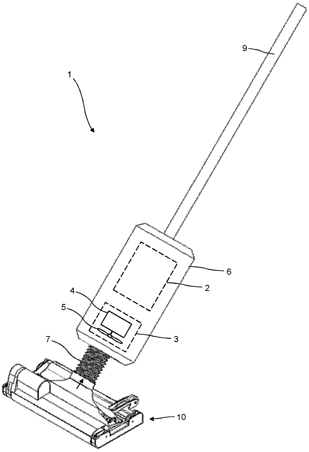
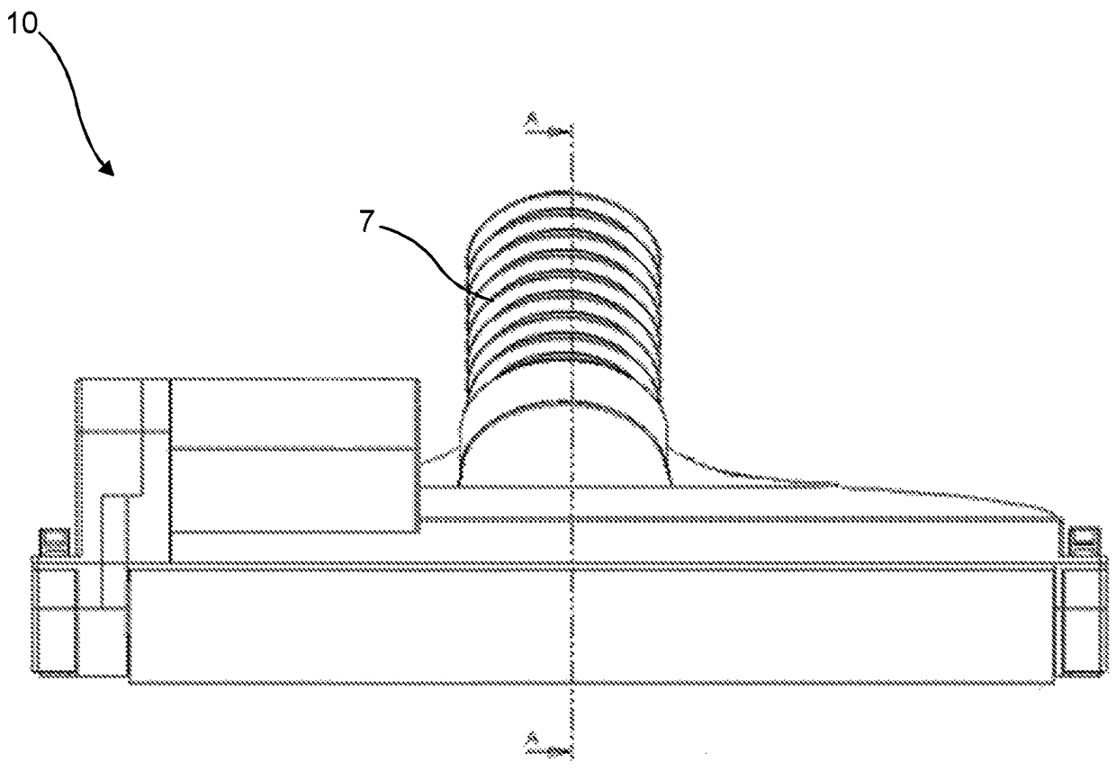
[0064] figure 1 A vacuum cleaner 1 is shown, comprising a cleaner head 10, a separation system 2, a suction source 3 and a tube 7 connected to the cleaner head 10. The separation system 2 and the suction source 3 can be installed in the housing 6. The vacuum cleaner 1 includes a handle 9 for pushing the cleaner head over the floor surface.

[0065] The tube 7 is fluidly connected to the cleaner head 10 and the separation system 2. The tube 7 is configured to transport dirty fluid (such as air) from the cleaner head 10 ...


PUM


Abstract

A cleaner head 10 for a vacuum cleaner has a suction inlet 20 defined in the lower face of a housing 11 and a suction passageway 20A through the housing 11. A rotatable sealing element 40 is located at a front of the housing 11. The rotatable sealing element 40 has a rotational axis 41 which is parallel to the lower face of the cleaner head. An agitator 60 is positioned rewards of the rotatable sealing element 40. The suction passageway 20A is located between the agitator 60 and the rotatable sealing element 40.

Description

Background technique [0001] Vacuum cleaners are a common form of household appliances. Nowadays, most vacuum cleaners operate in a similar way in principle. The vacuum cleaner includes a vacuum cleaner head (pickup head) that is pushed across the surface, a separation system that separates dirt / dust from the airflow, and a suction source (usually a motor and impeller) to generate the airflow. Dirt / dust is drawn from the surface to be cleaned and entrained in the airflow. The dirty airflow is drawn from the head of the vacuum cleaner to the separation system. Clean air is discharged into the room. When the air is expelled, negative pressure is formed on the pickup head. [0002] There are many variants of the separation system: (filter bag, cyclone separator and water tank) and the size and design of the motor. [0003] Different types of floor surfaces present different challenges. For carpeted floors, it is known to use a vacuum cleaner head with an agitator, such as a beati...

Claims


Application Information

Patent Timeline
Patent Type & Authority Applications(China)
IPC IPC(8): A47L9/02A47L9/04
CPCA47L9/02A47L9/0483A47L9/0488A47L9/0477A47L9/04
Inventor 路卡斯·霍恩帕布罗·蒙特罗-考威尔奥利弗·斯基特瑞
Owner LUPE TECH LTD
Why Eureka
Try Eureka