
Automatic conveying device for metal wires

A conveying device and metal wire technology, which is applied in the field of automation, can solve problems such as low work efficiency and unevenness, and achieve the effects of improving work efficiency, ensuring cleanliness, and avoiding damage

Inactive Publication Date: 2019-01-15
台州智子科技有限公司
View PDF6 Cites 3 Cited by
  • Summary
  • Abstract
  • Description
  • Claims
  • Application Information

AI Technical Summary

Problems solved by technology

[0003] Corresponding metal wires must be used in the production of electronic technology components. The metal wire conveying device is a common equipment in the production of electrical appliances, but the metal wires are often bent during transportation. The existing technology often uses stretching operations before operation. In this way, the metal wire is stretched through the cooperation of the clamping device and the feeding mechanism. However, although the overall shape of the metal wire can be changed in this way, there are still unevenness in some areas. It needs to be assembled with the electronic components before The secondary auxiliary correction has greatly reduced the work efficiency

Method used

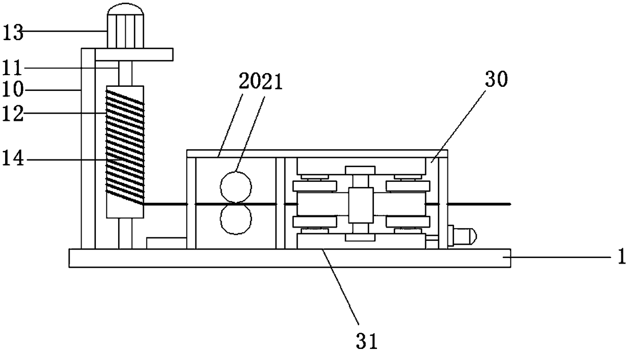

Image

  • Automatic conveying device for metal wires
  • Automatic conveying device for metal wires
  • Automatic conveying device for metal wires

Examples


Embodiment 1

[0023] An automatic conveying device for metal wire, please refer to figure 1 , Including a conveying seat 1, on which a conveying stand 10, a glue removal cavity 20 and a guide cavity 30 are installed, and a threading is provided between the conveying rack 10, the glue removal cavity 20 and the guide cavity 30 The conveying rack 10 is located at the front end of the conveying base 1, a conveying shaft 11 is vertically installed on the conveying rack 10, and a winding roller 12 is installed on the conveying shaft 11. A feeding motor 13 is installed at the top of the frame 10, and the feeding rotating shaft 11 is connected with the motor shaft of the feeding motor 13. The wire is wound on the winding roller 12, and the conveying motor 13 serves as a driving device for the conveying operation.

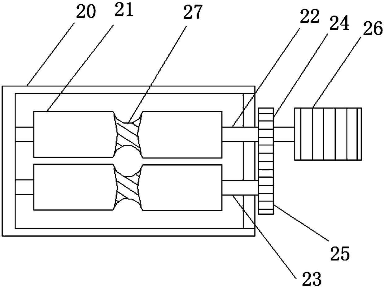
[0024] See figure 2 , The glue removal cavity 20 is located behind the conveying rack 10, and a glue removal roller 21 is installed in the glue removal cavity 20, and the glue removal roll...

Embodiment 2

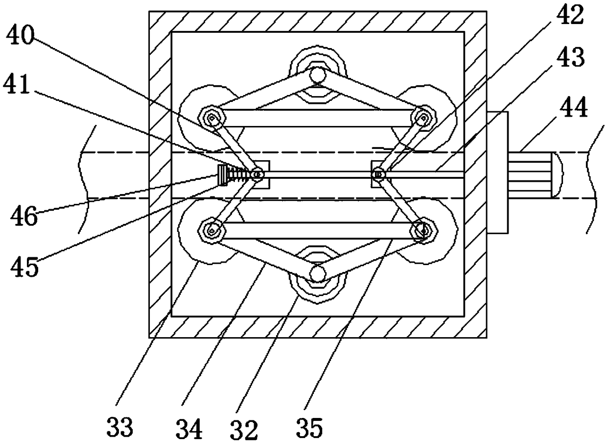
[0030] As a further optimization of the foregoing embodiment, on the basis of the first embodiment, the movable roller 33 includes an inner rod 51, an inner skin layer 52 and an outer skin layer 53, the inner rod 51 is mounted on the transmission frame 31, and the inner rod The skin layer 52 wraps the outer side of the inner rod 51, the outer skin layer 53 wraps the outer side of the inner skin layer 52, the inner skin layer 52 is installed with a compression spring 55, and the compression spring 55 supports the entire inner skin layer 52, so Several burrs 54 are installed on the outer side of the outer skin layer 53 at equal angles.

[0031] During operation, while the compression spring 55 supports the entire inner skin layer 52, it also acts as a buffer against the force of the outer skin layer 53 to avoid damage to the metal wire during limiting extrusion; the outer skin layer 53 is installed with several burrs 54, When in contact with the metal wire, clean the remaining powd...


PUM


Abstract

The invention discloses an automatic conveying device for metal wires, and relates to the technical field of automation. The automatic conveying device comprises a material conveying seat, the material conveying seat is provided with a material conveying frame, a colloid removing cavity and a guide cavity, the left side and the right side of the inner cavity of the guide cavity are provided with transmission frames, the outer ends of the transmission frames are provided with fixed rollers, the fixed rollers are fixedly arranged in the guide cavity, the front sides and the rear sides of the fixed rollers are provided with movable rollers, the movable rollers are movably arranged on the transmission frames, the movable rollers and the fixed rollers are connected through movable rods, the movable rollers on the left side are connected through fixing rods, the movable rollers on the right side are connected through fixing rods, the movable rollers which are not located on the same side left and right are connected through folding connecting rods, connecting blocks are arranged at the bending positions of the folding connecting rods, threaded grooves are formed in the connecting blocks,and threaded rods are arranged in the threaded grooves in a penetrating mode. According to the automatic conveying device, threaded transmission and connecting rod transmission mutually cooperate sothat the uneven areas of the metal wires can be pressed, and then the effect of the straight line body is achieved.

Description

Technical field [0001] The invention relates to the field of automation technology, in particular to an automatic conveying device for metal wires. Background technique [0002] Automation refers to equipment, systems or processes (production, management process) without the direct participation of people or fewer people, according to human requirements, through automatic detection, information processing, analysis and judgment, manipulation and control, to achieve the expected goals process. Automation technology is widely used in industry, agriculture, military, scientific research, transportation, commerce, medical care, services and households. The use of automation technology can not only liberate people from heavy physical labor, part of mental labor, and harsh and dangerous working environments, but also expand human organ functions, greatly increase labor productivity, and enhance human ability to understand and transform the world . [0003] Corresponding metal wires mu...

Claims


Application Information

Patent Timeline
IPC IPC(8): B21F1/02B21F23/00B24B27/033
CPCB21F1/02B21F23/00B24B27/033
Inventor 郑贝贝
Owner 台州智子科技有限公司
Learn More