

Shaving board hand-operated perforating device for furniture making
A technology for punching device and furniture manufacturing, which is applied to fixed drilling machines and other directions, can solve the problems of inconvenient punching operation, low efficiency of particle board punching operation, etc., and achieve the effect of improving efficiency
- Summary
- Abstract
- Description
- Claims
- Application Information
AI Technical Summary
Problems solved by technology
Method used
Image

Examples
Embodiment Construction
[0018] The preferred embodiments of the present invention will be described in detail below in conjunction with the accompanying drawings, so that the advantages and features of the present invention can be more easily understood by those skilled in the art, so as to define the protection scope of the present invention more clearly.
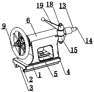
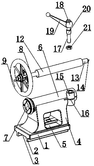
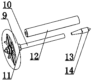
[0019] Such as Figure 1 to Figure 5 As shown, a hand-operated punching device for particleboard used in furniture manufacturing includes a base 1, a frame 4 is provided on the base 1, a guide cylinder 6 is provided on the top of the frame 4, and a guide cylinder 6 is provided at the axial position of the guide cylinder 6. The groove 7 and the position of the guide groove 7 are equipped with a rotating mechanism 8, the rotating mechanism 8 includes a rotating shaft 10 and a hand wheel 9, and the hand wheel 9 is connected to the rotating shaft 10; the outer peripheral surface of the rotating shaft 10 is equipped with a sleeve 12, and the sleeve 12 ...
PUM
 Abstract
Description
Claims
Application Information