
A rear conveying device for a shearing machine

A conveying device and post-conveying technology, applied in the field of shearing machine auxiliary processing devices, can solve problems such as low conveying efficiency, sheet material accumulation, and increase labor cost and labor intensity, and achieve high conveying efficiency, good stability, and improved conveying stability. Effects of Sexuality and Suitability

Active Publication Date: 2020-08-28
浙江天也智能科技有限公司
View PDF4 Cites 0 Cited by
  • Summary
  • Abstract
  • Description
  • Claims
  • Application Information

AI Technical Summary

Problems solved by technology

However, since there is no equipment on the market that collects and transports the sheets cut by the shearing machine, workers need to manually transport the sheets in the collection tank to the cart, and then rely on the cart to transfer the sheet to the Other workstations
This transportation method not only increases the labor cost and labor intensity of workers, but also easily causes the accumulation of sheets and the idle waiting of subsequent processing equipment when handling multiple sheets for the first time, and the transportation efficiency is low, which is not suitable for the current assembly line mode of production

Method used


Image

  • A rear conveying device for a shearing machine
  • A rear conveying device for a shearing machine

Examples


Embodiment Construction

[0014] The present invention will be further described below in conjunction with the accompanying drawings and embodiments, but not as a basis for limiting the present invention.

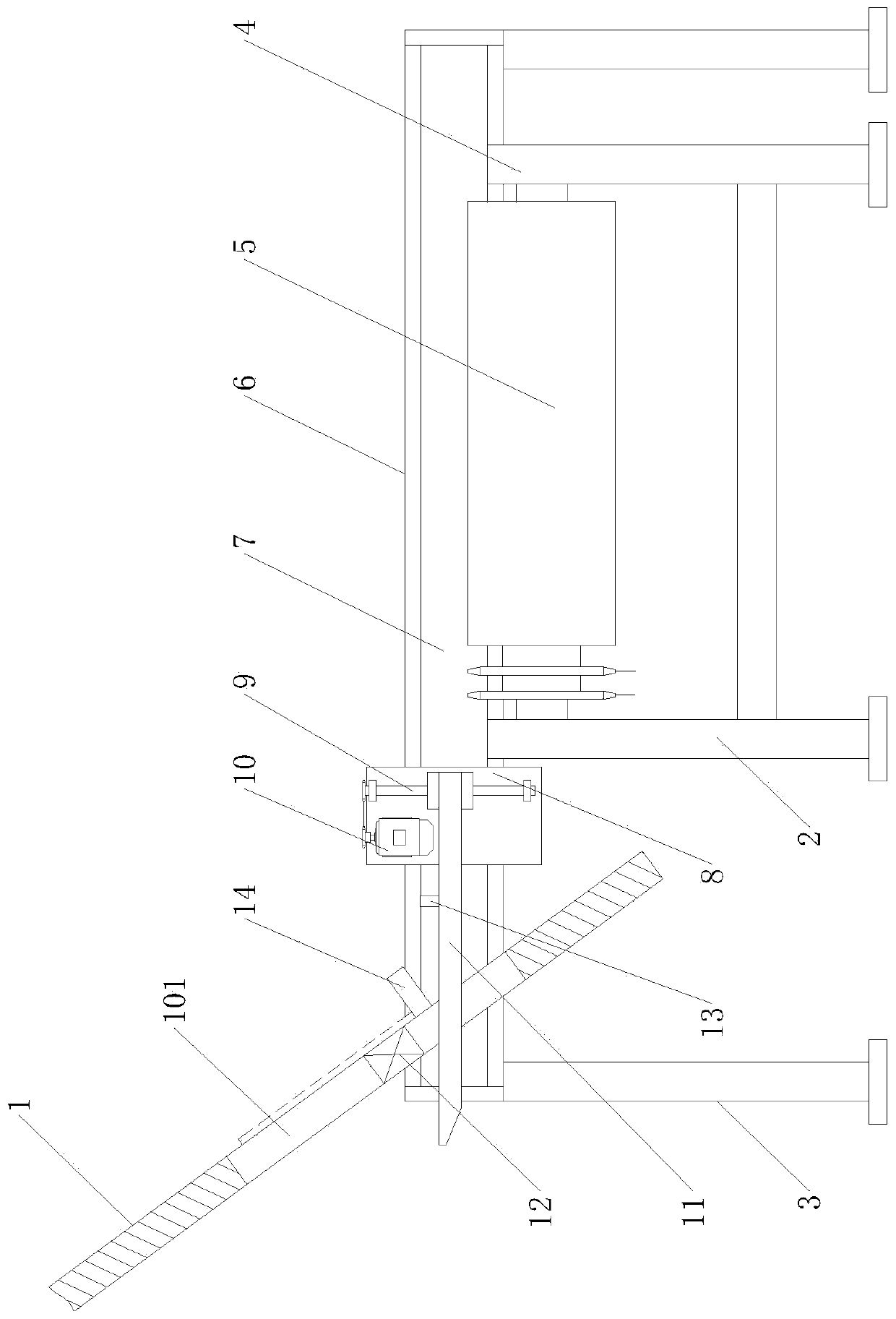
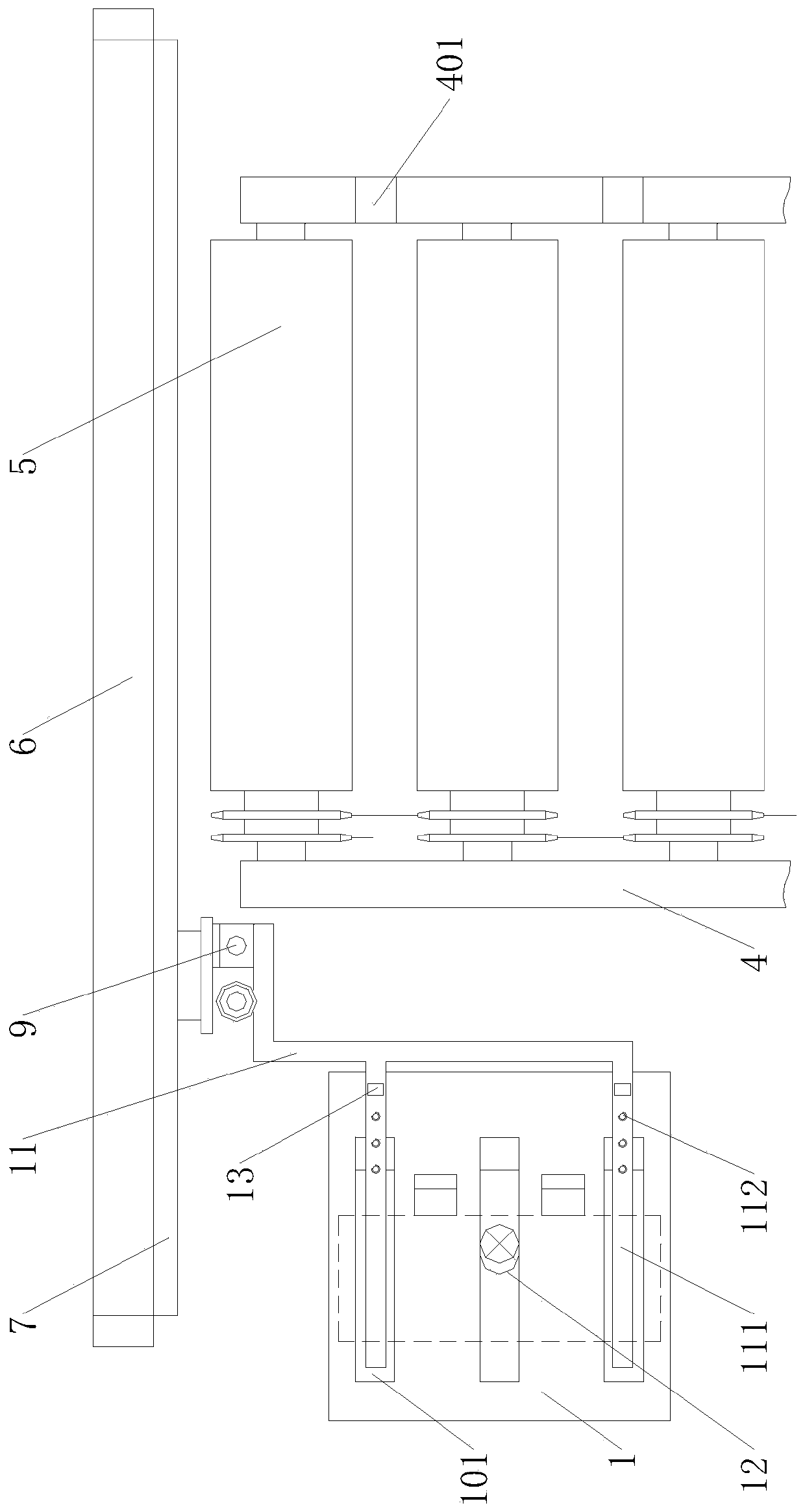
[0015] Example. A kind of conveying device behind the plate shearing machine, constituted as figure 1 As shown, including a slant plate 1, the lower end of the slant plate 1 is provided with a stopper 14, and a plurality of rectangular openings 101 are arranged at intervals on the slant plate 1. 2. The end of the conveying device 2 is provided with a pick-up device 3; the conveying device 2 includes a conveying frame 4, and a number of conveying cylinders 5 are uniformly distributed on the top of the conveying frame 4, and gaps are left between adjacent conveying cylinders 5; The pick-up device 3 includes a base 6 positioned outside the end of the conveyor frame 4, the upper end of the base 6 is connected to a pick-up seat 8 via a pneumatic slide 7, and a vertical ball screw 9 is arranged on the pi...


PUM


Abstract

The invention discloses a plate shearing machine rear conveying device. The conveying device comprises an inclined plate, a check block is arranged at the lower end of the inclined plate, multiple rectangular openings are distributed in the inclined plate at intervals, the lower ends of the rectangular openings extend to the position below the check block, a conveying device body is arranged on the outer side of the inclined plate, and a part taking device is arranged at the end of the conveying device body; the conveying device body comprises a conveying frame, multiple conveying cylinders are evenly distributed on the top of the conveying frame, and a gap is arranged between two adjacent conveying cylinders; the part taking device comprises a base located on the outer side of the end ofthe conveying frame, one side of the upper end of the base is connected with a part taking base through a pneumatic sliding table, a vertical ball screw is arranged on the part taking base, one end ofthe ball screw is connected with a driving motor through a chain wheel chain, and a part taking claw is connected with the ball screw through a screw nut. Plates can be ceaselessly collected and conveyed, the conveying efficiency is high, and stability is good.

Description

technical field [0001] The invention relates to a shearing machine auxiliary processing device, in particular to a shearing machine rear conveying device. Background technique [0002] The shearing machine is a machine that uses one blade to make a reciprocating linear motion relative to the other blade to cut the plate. The moving upper blade and the fixed lower blade exert shearing force on the metal sheets of various thicknesses, so that the sheets are broken and separated according to the required size; and the cut sheets freely fall to the bottom along the inclined plate outside the blade stored in collection tanks. However, since there is no equipment on the market that collects and transports the sheets cut by the shearing machine, workers need to manually transport the sheets in the collection tank to the cart, and then rely on the cart to transfer the sheet to the other workstations. This transportation method not only increases the labor cost and labor intensity...

Claims


Application Information

Patent Timeline
Patent Type & Authority Patents(China)
IPC IPC(8): B65H29/28B65H29/20
CPCB65H29/20B65H29/28
Inventor 应志鹏刘红英李书明
Owner 浙江天也智能科技有限公司
Learn More