Textile slitting machine based on industrial camera positioning

An industrial camera and slitting machine technology, which is applied in the cutting of textiles, papermaking, and textile materials, can solve the problems of not being able to accurately identify the position of the cutting seam, and achieve the effects of stable cutting quality, easy operation, and good recognition rate

Active Publication Date: 2019-01-15
高阳县高东电子科技有限公司
View PDF11 Cites 5 Cited by
  • Summary
  • Abstract
  • Description
  • Claims
  • Application Information

AI Technical Summary

Problems solved by technology

[0006] The present invention solves the technical problem that the prior art cannot accurately identify the position of the cutting seam during the cutting process by providing a textile slitting machine positioned by an industrial camera. Accurate positioning and tracking of the position of the cloth cutting seam, so as to achieve the technical effect of accurately cutting the cloth

Method used


Image

  • Textile slitting machine based on industrial camera positioning

Examples


Embodiment 1

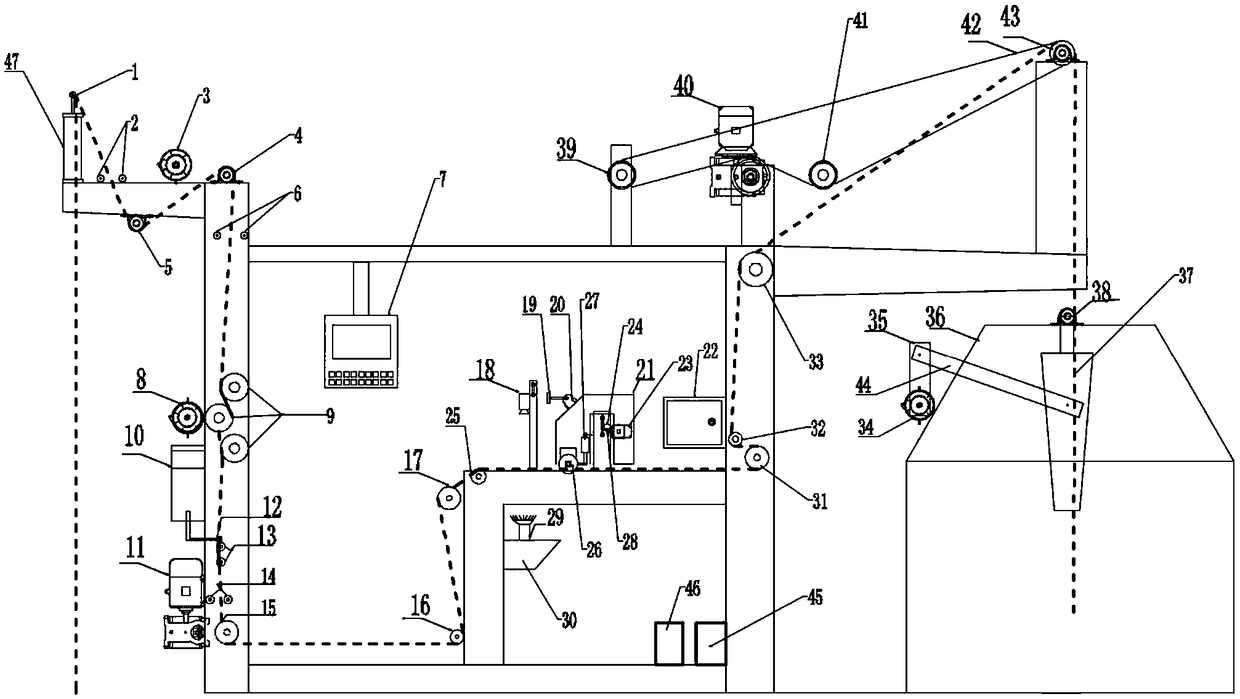
[0030] see figure 1 , the dotted line in the figure indicates the running track of the cloth. A textile slitting machine positioned by an industrial camera, which is sequentially equipped with a rough centering mechanism, a fine deviation correction mechanism, a flattening mechanism, a further deviation correction mechanism, a cloth feeding mechanism, a detection mechanism, a cutting mechanism and a cloth output mechanism from front to back; The coarse centering mechanism includes a first solenoid valve, a first cylinder 47, a centering rod 1 and a first centering light pipe 2, the first centering light pipe 2 is connected with the first solenoid valve, and the first solenoid The valve controls the first cylinder 47 to drive the centering rod 1 to move up and down. After the cloth enters the slitting machine equipment, the left and right deviation signal of the cloth is detected by the first centering optical tube 2, and the left and right deviation signal of the cloth is out...

Embodiment 2

[0040] In the above mentioned textile slitting machine positioned by the industrial camera, the main body frame of the slitting machine is also provided with a man-machine interface 7, and the man-machine interface 7 is connected to an industrial computer. The human-computer interaction interface 7 can display the real-time operating conditions of the equipment, and is also used to change the parameter settings, control the operation of the equipment through the industrial computer, or perform the start-stop operation of the equipment.

Embodiment 3

[0042] The slitting machine is also provided with a left and right mechanism, and the left and right mechanism is provided with a left and right motor 34 controlled by a frequency converter. The rocker arm 35 is connected, and the swing arm 35 is connected with the swing bucket 37 through the connecting rod 44, and the swing is completed through the swing bucket 37; the swing mechanism is also provided with a bracket 36, and the swing motor 34 is fixed on the bracket 36. The bucket 37 is fixed inside the bracket 36 through the left and right bucket bearings 38 . After cutting, the cloth is exported by the cloth outlet mechanism and then enters the swing mechanism. The swing motor 34 is controlled by a frequency converter. The frequency converter controls the swing frequency of the swing motor according to the frequency output by the PLC 46, thereby realizing the synchronization of the power system of the swing mechanism and the main machine of the slitting machine. , the left ...


PUM


Abstract

The invention, which belongs to the technical field of textile machinery equipment, provides a textile slitting machine based on industrial camera positioning. The textile slitting machine comprises acoarse centering mechanism, a fine deviation correcting mechanism, a flattening mechanism, a re-correcting mechanism, a feeding mechanism, a detecting mechanism, a cutting mechanism and the like thatare arranged successively from front to back. The detecting mechanism includes a backlight emitter, an industrial camera and an industrial personal computer; the backlight emitter is arranged below apiece of cloth and is used for emitting a light source to the cloth; and the industrial camera captures an opening slit on the cloth and a surrounding environment pixel difference, and transmits thepixel difference information to the industrial personal computer for processing through wired communication. The cutting mechanism includes a cutter, a servo motor and a lifting cylinder; the servo motor controls the cutter to move left and right based on cooperation of a gear and a rack. Compared with the infrared radiation positioning, the industrial camera positioning enables the recognition rate and the detection precision to be improved; visual image information can be provided; and thus the worker can operate the machine easily.

Description

technical field [0001] The invention belongs to the technical field of textile machinery and equipment, and in particular relates to a textile slitting machine positioned by an industrial camera. Background technique [0002] In the production process of towel quilt textiles, washing and dyeing finishing process will be involved. The end link of this process is the longitudinal cutting process of the product. At present, the cutting process is mainly completed in the following ways. [0003] (1) Manual cutting. The cloth runs longitudinally on the simple equipment, and the knife is manually held, and the specific opening and cutting seam position of the cloth is aligned with the cooperation of eyes and hands for cutting. It mainly relies on years of operating experience to perceive the subtle changes in the feedback of the cutter and judge the cutting Is the location correct. This method will be affected by many factors, such as the folds during the movement of the cloth, ...

Claims


Application Information

Patent Timeline
Patent Type & Authority Applications(China)
IPC IPC(8): D06H7/04
CPCD06H7/04
Inventor 李巨鹏
Owner 高阳县高东电子科技有限公司
Why Eureka
Try Eureka