Assembly type double-point fixed foundation pit bridleway structure and construction method thereof

A combined, foundation pit technology, applied in the direction of foundation structure engineering, excavation, building construction, etc., can solve the problems of high risk factor of foundation pit, repeated demolition of horse roads, repeated construction procedures, etc., to achieve reasonable stress and structure. Simple, reduced slip overturning effect

Pending Publication Date: 2019-01-15
BEIJING NO 3 CONSTR ENG
0 Cites 0 Cited by

AI-Extracted Technical Summary

Problems solved by technology

[0003] The purpose of the present invention is to provide a combined two-point fixed foundation pit horse track structure and its construction method to solve the need to remove the horse track many times when excavating earthwork layer by layer, resulting in repeated construction procedures, affecting the construction period, and causing unnecessary delays. ...

Method used

As shown in Figures 9 to 12, the vertical beam (33) is a double channel steel, on which the fourth connection hole (12) is provided, and the vertical beam (33) is provided with an adjustable base connector (7) , the adjustable base connector (7) includes a steel sleeve (71) and a vertical beam connecting plate (72) welded on both sides of the steel sleeve (71), the vertical beam connecting plate (72) is provided with a vertical beam ( 33) The fifth connection hole (13) connected, the steel sleeve (71) passes through the fourth connection hole (12) on the vertical beam (33), and the vertical beam connecting plate (72) is fixedly connected to the vertical beam (33) The inner side of the two channel steel. The adjusting base (37) ...

Abstract

The invention discloses an assembly type double-point fixed foundation pit bridleway structure, which comprises a terrace concrete beam, a pile top concrete beam, a bridleway bracket and a bridleway frame body. The bridleway frame body is connected with the bridleway bracket and extends downwards or upwards along the side wall of a foundation pit. The bridleway bracket comprises a bridleway bracket unit and a horizontal cross beam. The bridleway bracket unit comprises a first horizontal longitudinal beam, a second horizontal longitudinal beam, a vertical beam, a first inclined support, a second inclined support and an adjusting base. The foundation pit bridleway structure is connected with a profile steel bridleway bracket through a bridleway frame body. The bridleway bracket serves as a main fixing device for the force bearing and the force transmission of the foundation pit bridleway. The bridleway bracket is fixedly connected with the terrace concrete beam and the pile top concretebeam, so that the pull force applied by a single-point fixed bridleway to the foundation pit can be balanced. The bridleway bracket can reduce slippage and overturning of the slope protection pile into the foundation pit, and plays a good role in protecting the foundation pit.

Application Domain

ExcavationsShaping building parts

Technology Topic

Pull forceSingle point +1

Image

  • Assembly type double-point fixed foundation pit bridleway structure and construction method thereof
  • Assembly type double-point fixed foundation pit bridleway structure and construction method thereof
  • Assembly type double-point fixed foundation pit bridleway structure and construction method thereof

Examples

  • Experimental program(1)

Example Embodiment

[0045] In order to make the technical means, innovative features, objectives and effects achieved by the present invention easy to understand, the present invention will be further explained below.
[0046] The embodiments described herein are specific specific implementations of the present invention, which are used to illustrate the concept of the present invention. They are all explanatory and exemplary, and should not be construed as limiting the embodiments of the present invention and the scope of the present invention. In addition to the implementation exceptions described here, those skilled in the art can also adopt other obvious technical solutions based on the content disclosed in the claims and specification of this application. These technical solutions include adopting any obvious changes to the embodiments described herein. Technical solutions for replacement and modification.
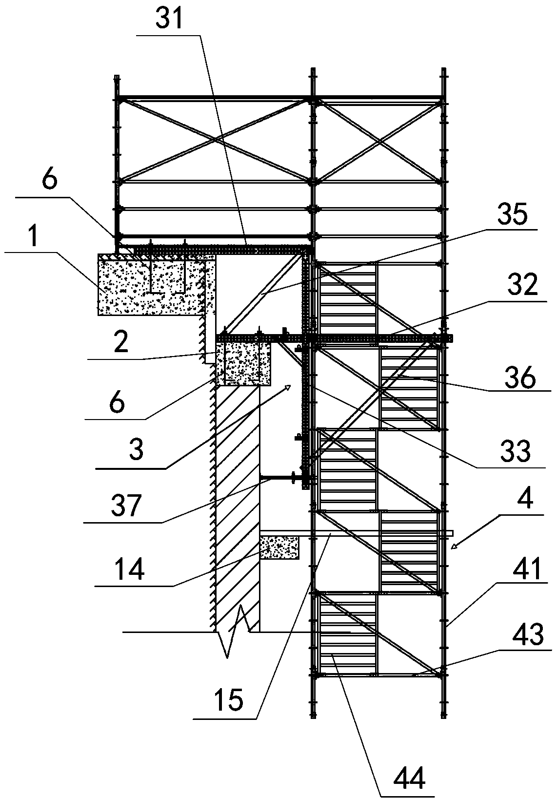
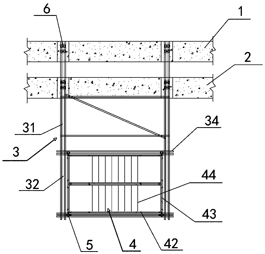
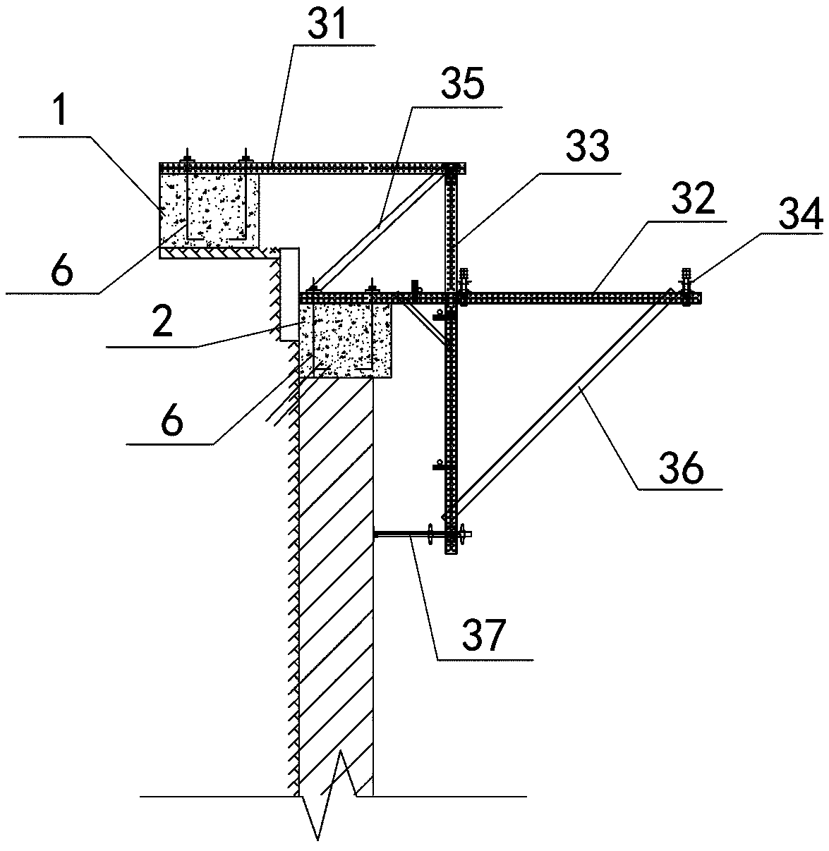
[0047] Such as Figure 1~4 As shown, the assembled two-point fixed foundation pit horse track structure includes floor concrete beam (1), pile top concrete beam (2), horse track bracket (3) and horse track frame (4), floor concrete beam (1) ) And the pile top concrete beam (2) are equipped with embedded parts (6), the embedded parts (6) are anchor bolts, and the anchor bolts are made of fine-rolled rebar. The carriage body (4) is connected with the carriage bracket (3) and extends downward or upward along the side wall of the foundation pit.
[0048] The carriage carriage (3) includes at least two carriage carriage units and a horizontal beam (34) connected between the carriage carriage units. The carriage carriage unit includes a first horizontal longitudinal beam (31) and a second horizontal longitudinal beam ( 32), vertical beam (33), first diagonal brace (35), second diagonal brace (36) and adjustment base (37). The first horizontal longitudinal beam (31), the second horizontal longitudinal beam (32) and the vertical beam (33) are all provided with adjusting holes (8). The first horizontal longitudinal beam (31) is double-split channel steel. The first horizontal longitudinal beam (31) is fixedly connected to the embedded part (6) in the floor concrete beam (1) through a straight threaded sleeve or nut, and the One end of a horizontal longitudinal beam (31) is fixedly connected with the top of the vertical beam (33). The second horizontal longitudinal beam (32) is fixedly connected to the embedded part (6) in the pile top concrete beam (2) through a straight threaded sleeve or nut, and the second horizontal longitudinal beam (32) is connected to the vertical beam (33) , The horizontal beam (34) is placed on the second horizontal longitudinal beam (32) and connected with the second horizontal longitudinal beam (32). The first diagonal brace (35) is connected between one end of the second horizontal longitudinal beam (32) and the top of the vertical beam (33), and the second diagonal brace (36) is connected to the other end of the second horizontal longitudinal beam (32) And the bottom of the vertical beam (33).
[0049] The adjusting base (37) is arranged horizontally, one end of the adjusting base (37) is connected with the side wall of the foundation pit, and the other end is connected with the vertical beam (33).
[0050] Such as Figure 5 As shown, the horse track frame body (4) is formed by splicing unit ladders. The unit ladders include a frame surrounded by vertical rods (41), horizontal cross bars (42) and horizontal vertical rods (43). Ladder (44), handrails, resting platform and protective net in the frame. The upright rod (41) of the unit ladder section close to the second horizontal longitudinal beam (32) is connected with the horse track bracket (3) through the upright rod connector (5).
[0051] Such as Figure 6-8 As shown, the second horizontal longitudinal beam (32) and horizontal beam (34) are both double-split channel steel, the second horizontal longitudinal beam (32) is provided with a first connecting hole (9), and the horizontal beam (34) is provided There is a second connecting hole (10), the vertical rod connecting piece (5) passes through the first connecting hole (9) and the second connecting hole (10), and both ends of the vertical rod connecting piece (5) are connected to the vertical rod (41). ) Connection, and further connect the vertical rod (41) with the second horizontal longitudinal beam (32) and the horizontal cross beam (34). The vertical rod connector (5) includes an intermediate rod (51) and connecting plates (52) arranged at both ends of the intermediate rod (51). The connecting plate (52) is provided with a third connecting hole ( 11). A limit plate (53) is also provided between the connecting plate (52) and the intermediate rod (51), and the width of the limit plate (53) is larger than the aperture of the first connecting hole (9) and the second connecting hole (10). Install the pole connector (5) on the horse track bracket (3) to connect the horse track frame (4) upward or downward from the horse track bracket (3) to form a mirror effect to meet special foundation pits or The demand for upward construction in special construction situations. In addition, the pole connector (5) can be recycled.
[0052] Such as Figure 9-12 As shown, the vertical beam (33) is a double-split channel steel with a fourth connecting hole (12) provided on the vertical beam (33), an adjustable base connector (7), an adjustable base connector (7) ) Includes a steel sleeve (71) and a vertical beam connecting plate (72) welded on both sides of the steel sleeve (71). The vertical beam connecting plate (72) is provided with a fifth connecting hole connected to the vertical beam (33) (13) The steel sleeve (71) passes through the fourth connecting hole (12) on the vertical beam (33), and the vertical beam connecting plate (72) is fixedly connected to the inner side of the two channel steels of the vertical beam (33). The adjusting base (37) includes a screw (371), a first nut (372) and a second nut (373) that are matched with each other. The screw (371) passes through the first nut (372) and the steel sleeve (71), and is connected with The second nut (373) is threaded. The vertical beam (33) of the carriage bracket (3) is connected with an adjusting base (37), which is in contact with the slope protection piles of the foundation pit, so that the carriage body (4) can be fixed at any distance from the edge of the foundation pit. ) The bending moment received is transmitted to the soil to prevent the equestrian frame (4) from overturning, and avoid material waste caused by the need to replace the adjustable base due to distance changes.
[0053] In addition, during the connection process of the horse track frame body (4), a unit ladder section wall attachment device (15) must be installed between the horse track frame body (4) and the purlin beam (14) on the side wall of the foundation pit. Paragraph to pull knot.
[0054] Figure 13 It is a simplified diagram of the force analysis of the single horse track support element (except the first horizontal longitudinal beam). The force analysis shows that point B (at the adjustable base) exerts pressure on the slope protection pile, and point A (the concrete on the top of the pile) The beam) is applied to the slope protection pile in the pulling force and upward pulling force, because the pulling force applied to the slope protection pile at point A is in the same direction as the squeezing direction of the soil body outside the foundation pit, and the slope protection pile is at point A Under tension and compression at point B, a bending moment is formed as a whole, which is extremely unfavorable to the safety of slope protection piles and foundation pits. Therefore, concrete beams are poured on the ground and connected to the carriage bracket (except the first horizontal longitudinal beam) through the first horizontal longitudinal beam (31). At this time, the force analysis shows that the carriage body is pulled apart into the foundation pit. The forces have been balanced, so the slope protection pile at point A is no longer pulled into the foundation pit. Reduce the slip and overturn of the slope protection pile into the foundation pit, and protect the foundation pit. Based on the force analysis of the single-horse carriage support unit (except the first horizontal longitudinal beam), on the one hand, it can be calculated whether the material of the bracket body meets the force requirements, and the overall structure of the bracket is safe. On the other hand, the force and direction of the horse track bracket on the slope protection pile can be derived from the force of the horse track bracket. Because the bracket pulls the slope protection pile into the foundation pit, a pulling force in the opposite direction is applied on the ground. , Balance the pulling force of the slope protection pile to ensure the safety of the foundation pit.
[0055] The construction method of the above-mentioned assembled two-point fixed foundation pit horseway structure includes the following steps:
[0056] Step 1. Preliminary preparation: Determine the maximum lap length of the horse track frame (4) according to the shear strength of the bolts between the unit steps, and determine the resistance of the embedded parts according to the maximum dead weight of the horse track frame (4) and the construction load. Tensile strength and size; at the same time, specify the tensile strength requirements of concrete and determine the marks and sizes of the floor concrete beam (1) and the pile top concrete beam (2).
[0057] Step 2: Install the carriage bracket (3): first connect the vertical beam (33) and the adjusting base (37) into a whole by bolts; then connect the second horizontal longitudinal beam (32) with the vertical beam (33); A diagonal brace (35) and a second diagonal brace (36); connect the single carriage unit without the first horizontal longitudinal beam (31) through the horizontal beam (34); connect the first horizontal longitudinal beam (34) without The carriage bracket (3) of the beam (31) is fixed on the concrete beam (2) on the top of the pile; finally the first horizontal longitudinal beam (31) is installed, and one end of the first horizontal longitudinal beam (31) is connected to the floor concrete beam (1). ) It is fixed by anchor bolts, and the other end is connected with the vertical beam (33).
[0058] Step 3. Install the unit ladder: Enclose and assemble the vertical pole (41), horizontal cross bar (42) and horizontal vertical bar (43) into a frame, and then install the ladder (44) and diagonal bars in the frame, install the handrails, Platform railings and protective nets, etc.
[0059] Step 4. Connect the unit stairs to the carriage bracket (3): the vertical rod connector (5) passes through the holes on the second horizontal longitudinal beam (32) and horizontal beam (34), and then the vertical rod (41) It is connected with the two ends of the vertical rod connector (5), and then the vertical rod (41) is connected with the second horizontal longitudinal beam (32) and the horizontal beam (34) of the horse track bracket (3).
[0060] Step 5. Assembling unit ladders: Assemble unit ladders on the upper and/or lower part of the carriage bracket (3) along the sidewall of the foundation pit according to construction needs. The unit steps are connected by bolts.
[0061] Step 6. Set up the horse track wall attachment device (15): install the horse track wall attachment device (15) between the unit stairs and the purlin beam (14) on the side wall of the foundation pit to tie the horse track frame (4) . The horse road wall attached device (15) can choose the frame body to surround the steel beam.
[0062] Step 7. Install the head guard and construction access road: Install the head guard and construction access road on the top of the platform, and the foundation pit horse road is installed.
[0063] The steps to remove the above-mentioned horse track structure are opposite to the installation steps, that is, first remove the horse track steps and ladders, then remove the diagonal rods, horizontal rods and vertical rods, and finally remove the brackets.
[0064] The above embodiments only describe the preferred embodiments of the present invention, and do not limit the scope of the present invention. Without departing from the design spirit of the present invention, various modifications made by those skilled in the art to the technical solutions of the present invention All improvements and improvements shall fall within the protection scope determined by the claims of the present invention.

PUM

no PUM

Description & Claims & Application Information

We can also present the details of the Description, Claims and Application information to help users get a comprehensive understanding of the technical details of the patent, such as background art, summary of invention, brief description of drawings, description of embodiments, and other original content. On the other hand, users can also determine the specific scope of protection of the technology through the list of claims; as well as understand the changes in the life cycle of the technology with the presentation of the patent timeline. Login to view more.

Similar technology patents

Air bag module

InactiveUS20070057487A1simple structureeasily manufacture
Owner:HYUNDAI MOBIS CO LTD

Biometric identification apparatus

InactiveUS20080037001A1perform accurately and rapidlysimple structure
Owner:HITACHI MEDIA ELECTORONICS CO LTD

Body condition measuring device

InactiveUS20050234351A1simple structure
Owner:DENSO CORP

Classification and recommendation of technical efficacy words

  • Simple structure

Sharing system for air-conditioning coat

InactiveCN107440179ASimple structureeasy to wear
Owner:QINGDAO HAIER AIR CONDITIONER GENERAL CORP LTD

Feeding device of sorter of batteries plate

InactiveCN101357717ASimple structurecooperate well
Owner:NANJING NORMAL UNIVERSITY

Emergency parachuting device and method for multiple-rotor unmanned aerial vehicle

InactiveCN103895870Aavoid aircraft crashSimple structure
Owner:SOUTH CHINA AGRI UNIV +1

Quick pipe connector

Owner:YANG RICHARD
Why Eureka
Try Eureka