Helium turbine casing structure

A technology of air intake casing and turbine casing, which is applied in the direction of machines/engines, mechanical equipment, engine components, etc. It can solve the problems of large and not compact casing mechanism, achieve good assembly and disassembly, improve the initial temperature of intake air, and ensure safety The effect of reliable work

Pending Publication Date: 2019-01-15
中国船舶重工集团公司第七0三研究所
View PDF0 Cites 0 Cited by
  • Summary
  • Abstract
  • Description
  • Claims
  • Application Information

AI Technical Summary

Problems solved by technology

[0003] The purpose of the present invention is to solve the problem that the existing casing mechanism is bulky and not compact, and then provide a helium turbine casing structure

Method used


Image

  • Helium turbine casing structure
  • Helium turbine casing structure
  • Helium turbine casing structure

Examples


specific Embodiment approach 1

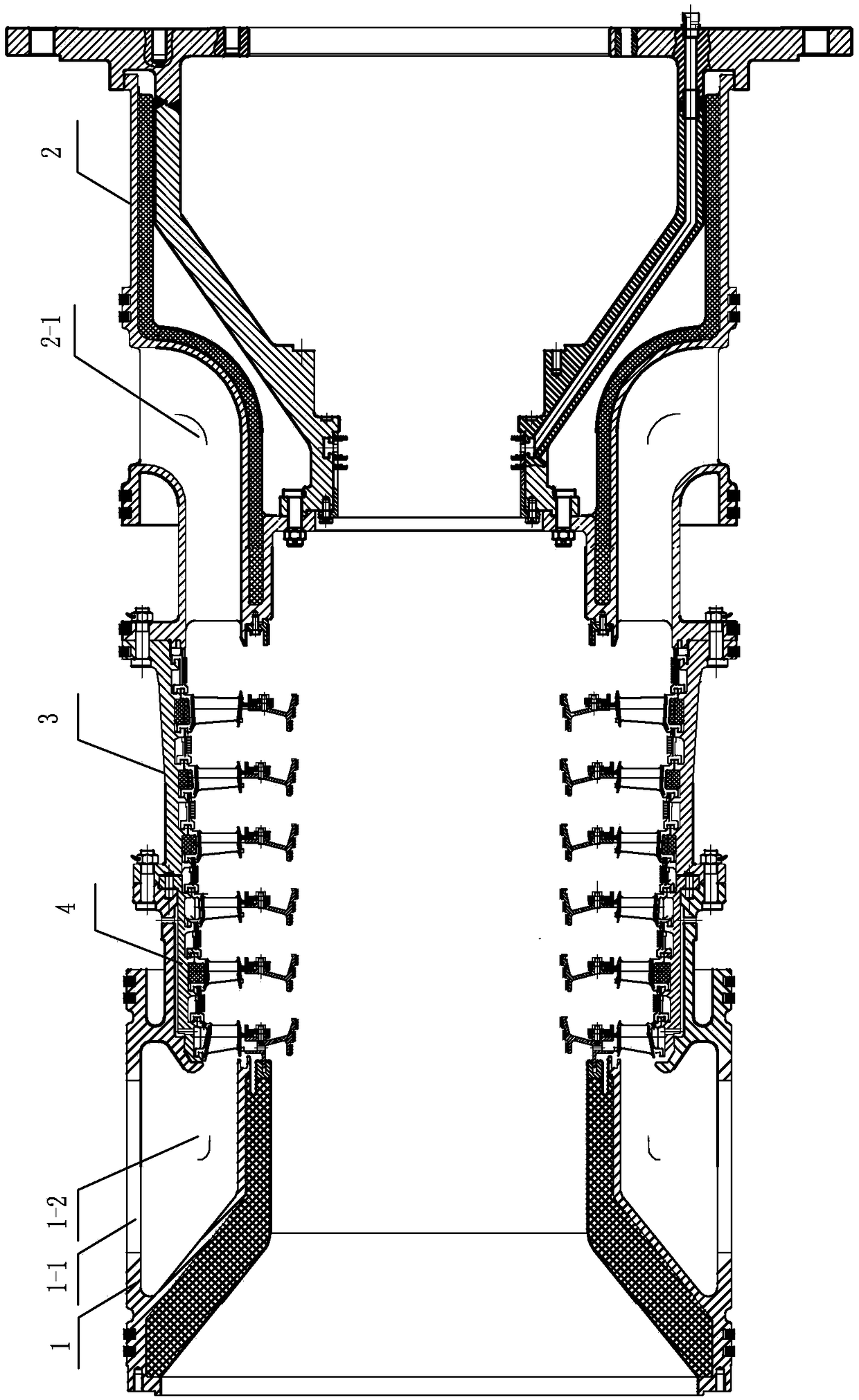
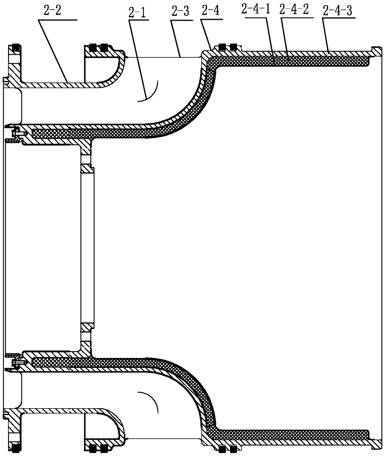
[0021] Specific implementation mode one: combine Figure 1 to Figure 3 Describe this embodiment, this embodiment includes intake casing 1, inner casing 4, exhaust casing 2 and turbine casing 3, intake casing 1, turbine casing 3, exhaust casing 2 are connected end to end in sequence, the inner The casing 4 is installed in the inside of the intake casing 1, and the upper surface and the lower surface of the intake casing 1 are respectively provided with an air inlet 1-1, and the air inlet 1-1 is connected with the air inlet casing 1. The cavity forms an air intake passage 1-2, and the outer wall of the exhaust casing 2 is provided with a plurality of air outlet passages 2-1 along the circumferential direction. The intake casing has no intake guide plate, and the intake port 1-1 can make the gas flow more smoothly and increase the intake volume. The connection of intake casing, turbine casing and exhaust casing adopts a bolt tension structure, which is easy to assemble and disas...

specific Embodiment approach 2

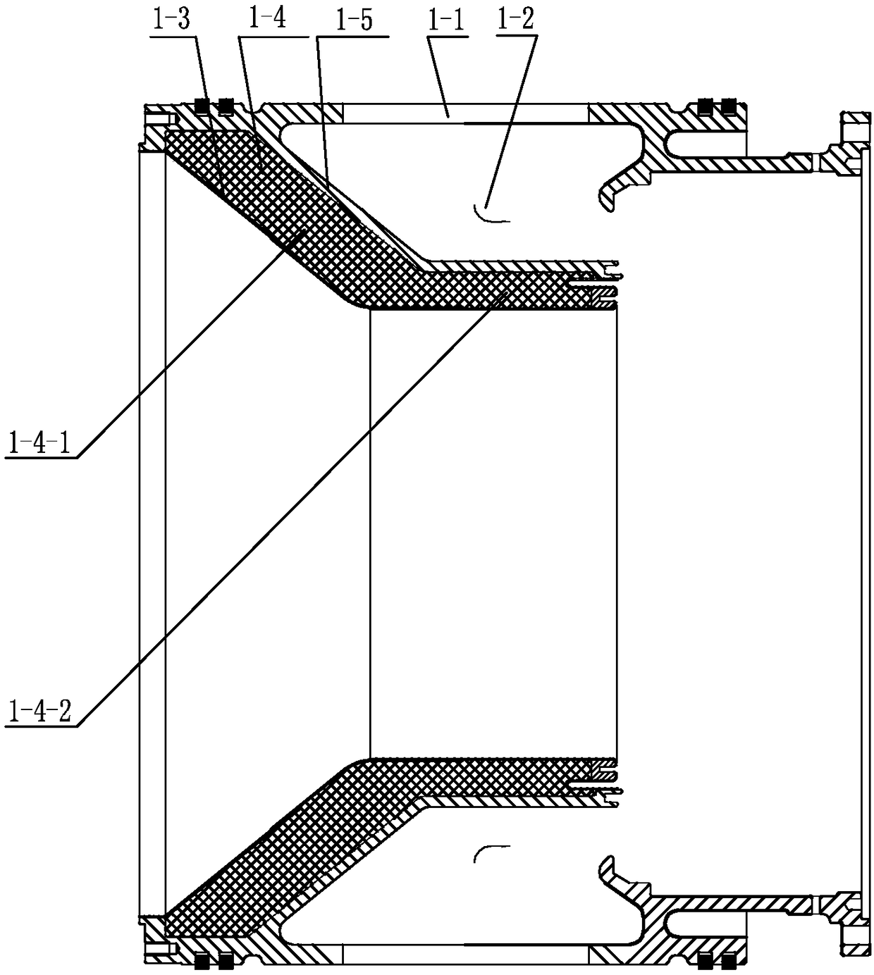
[0022] Specific implementation mode two: combination Figure 1 to Figure 3 Describe this embodiment, the air intake casing 1 of this embodiment includes a first steel plate 1-3, a first heat insulation layer 1-4 and an intake volute 1-5, a first steel plate 1-3, a first heat insulation layer Layers 1-4 and intake volutes 1-5 are arranged sequentially from inside to outside. Other compositions and connections are the same as in the first embodiment. The air intake casing with thermal insulation structure can meet the strength requirements of use, achieve the required heat insulation effect, ensure that the initial temperature of the inlet meets the design temperature, and ensure that it can work safely and reliably under high temperature for a long time. Other compositions and connections are the same as in the first embodiment.

specific Embodiment approach 3

[0023] Specific implementation mode three: combination Figure 1 to Figure 3 To illustrate this embodiment, the thickness of the inclined section 1-4-1 of the first thermal insulation layer 1-4 in this embodiment is greater than the thickness of the horizontal section 1-4-2. Other compositions and connections are the same as those in the second embodiment.


PUM

PropertyMeasurementUnit
Diameteraaaaaaaaaa

Abstract

The invention discloses a helium turbine casing structure, which relates to a casing structure and aims at solving the problem that the existing casing mechanism is huge and not compact. The helium turbine casing structure comprises an air intake casing, an inner casing, an exhaust casing and a turbine casing. The air intake casing, the turbine casing and the exhaust casing are connected sequentially in an end-to-end mode; the inner casing is installed inside the air intake casing; each of the upper and lower surfaces of the air intake casing is respectively provided with a symmetrical air intake port; the air intake port and the cavity in the air intake casing form an air intake channel; the outer wall of the exhaust casing is provided with multiple air outlet channels along the circumference direction. The helium turbine casing structure is applied to the technical field of helium turbines.

Description

technical field [0001] The invention relates to a casing structure of a helium gas turbine, which is applied in the technical field of helium gas turbines. Background technique [0002] The casing is an important part of the helium turbine, which is used in the helium turbine in the nuclear reactor. In the past, the compressor and the turbine were separated, and the mechanism was large and not compact. The compressor and turbine of the helium turbine designed now are integrated, so it is necessary to design a new and reasonable casing structure to adapt to the application of the helium turbine. If the casing design is unreasonable, sometimes the pressure loss will be too large, and Reasonable design of the casing can ensure the smoothness and uniformity of the inlet of the moving blade. Contents of the invention [0003] The purpose of the present invention is to solve the problem that the existing casing mechanism is bulky and not compact, and further provide a helium tu...

Claims


Application Information

Patent Timeline
IPC IPC(8): F01D25/24F01D25/14
CPCF01D25/145F01D25/24F01D25/243
Inventor 郁顺旺朱凯迪刘勋马涛张馨舒春英
Owner 中国船舶重工集团公司第七0三研究所
Why Eureka
Try Eureka