Fully automatic probe detection bench and probe positioning module thereof

A technology of probe detection and positioning mode, applied in the direction of measuring electricity, measuring device, measuring electrical variables, etc., can solve the problems of low efficiency and difficulty in aligning the needle with the probe card, and achieve high detection efficiency without affecting the performance of the workbench. High-resolution imaging

Active Publication Date: 2019-01-15
SHENZHEN SIDEA SEMICON EQUIP
View PDF6 Cites 7 Cited by
  • Summary
  • Abstract
  • Description
  • Claims
  • Application Information

AI Technical Summary

Problems solved by technology

[0003] The traditional calibration system uses manual observation through a microscope to control the mobile worktable so that a specific point on the wafer corresponds to the probe on the probe card above it (the probe card is placed above the workbench, and the microscope is located on the probe The traditional needle alignment method, due to the limited field of view of the microscope, it is difficult to align the probe cards with a large number of probes. The needle alignment accuracy and contact height are completely controlled manually, and the efficiency is low.

Method used


Image

  • Fully automatic probe detection bench and probe positioning module thereof
  • Fully automatic probe detection bench and probe positioning module thereof
  • Fully automatic probe detection bench and probe positioning module thereof

Examples


Embodiment 1

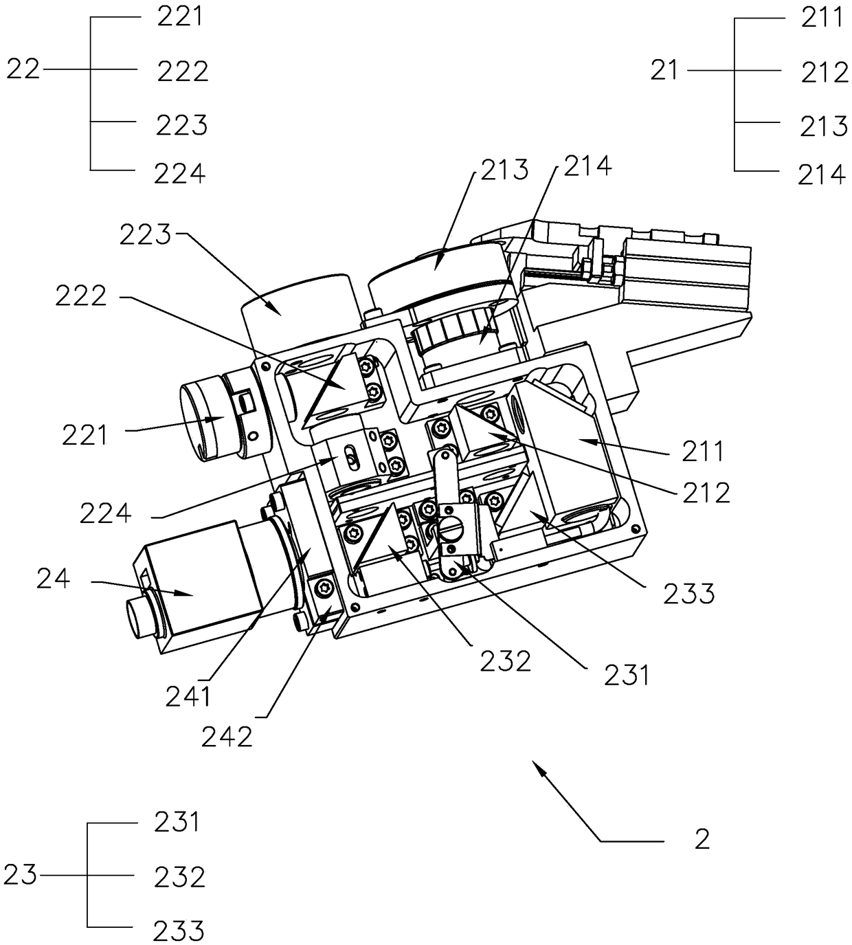
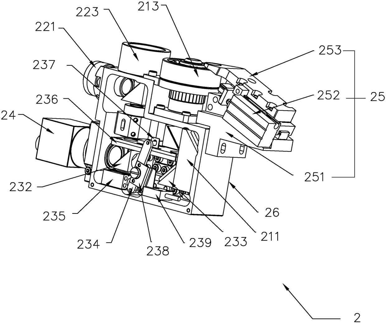
[0047] Embodiment 1: A probe positioning module, refer to figure 1 and figure 2 , comprising a probe detection box 26 fixed on the workbench, the probe detection box 26 is provided with a low-power light source detection module 22, a high-power light source detection module 21, an optical path switching module 23, a CCD image sensor 24 and a target adjustment module 25 .

[0048] refer to figure 1 , the low power source detection module 22 includes a low power ring light source 223 fixed on the probe detection box 26, a low power point light source 221, a low power beam splitter 222 and a low power lens 224, a low power ring light source 223 and a low power point light source 221 are respectively installed on the outer sides of the mutually perpendicular side walls, and the low-magnification ring light source 223 faces directly upward. The center of the low-magnification ring light source 223 has a low-magnification point light source 221 emission hole, and the low-magnifi...

Embodiment 2

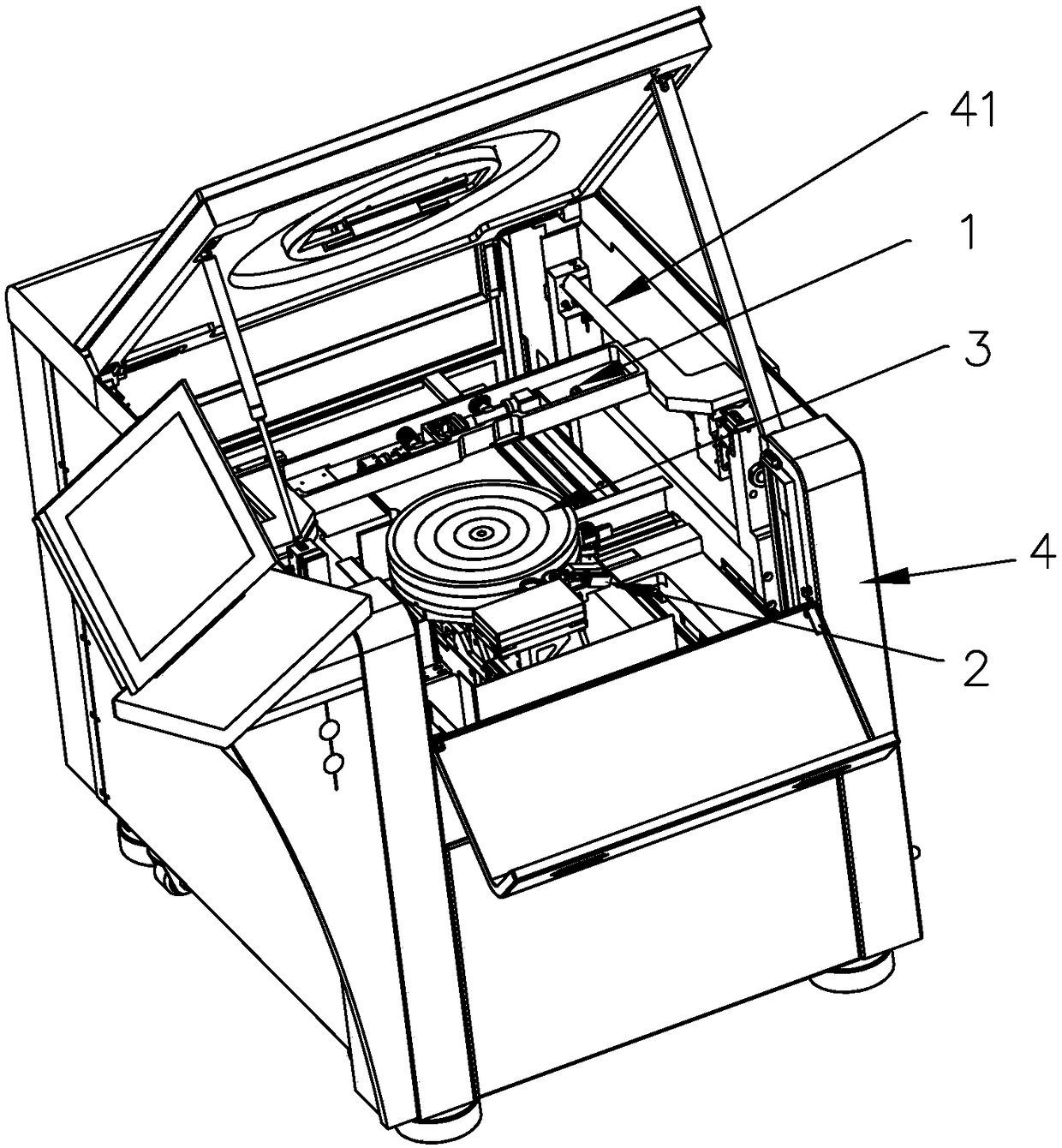
[0056] Embodiment 2: a kind of automatic probe detection platform, as image 3 As shown, it includes the chip positioning module 1 and the probe positioning module 2 in Embodiment 1, which are used for the probe positioning of the probe detection station. The probe detection station includes a body 4, a workbench 3 and a machine cover, and the machine cover A probe card is installed on it. The workbench 3 moves in the three directions of X, Y and Z in the box. Horizontal sliding rods 41 are fixed on the inner walls of both sides of the box, and the horizontal sliding rods 41 are slidably connected to the chip positioning module 1 .

[0057] refer to Figure 4 and Figure 5 The chip positioning module 1 includes a high power mirror module 12 , a low power mirror module 11 , a chip optical path module 13 and a height detection module 14 . The high power mirror module 12 includes a chip CCD sensor, a high power mirror and a high power light source. The high power mirror leads...


PUM


Abstract

The invention discloses a probe positioning module, comprising a probe detection box. The probe detection box is provided with a high-power light source detection module, a low-power light source detection module, a CCD image sensor, an optical path switching module, and a target adjustment module. The optical path switching module comprises a high and low-power optical path beam splitter leadingto the CCD image sensor, a mirror for guiding the light to the high and low-power beam splitter, and a high and low-power switching mechanism. Through the above settings, the low-power light source detection module is used for detection when the invention is used. When the CCD image sensor detects that the probe is in position, a switching cylinder is controlled to act, drives a shielding plate isdriven to move, and the high-power light source detection module is switched. There is no need to set probe card parameters so that the detection efficiency is high. The invention further discloses afully automatic probe detection bench using the probe positioning module.

Description

technical field [0001] The invention relates to the field of chip detection equipment, in particular to a fully automatic probe detection platform and a probe positioning module. Background technique [0002] The automatic probe station is a special equipment for semiconductor testing. It uses a probe to touch a specific point on the wafer for probe testing; the premise that the probe touches a specific point on the wafer needs to be manually or automatically matched. [0003] The traditional calibration system uses manual observation through a microscope to control the mobile worktable so that a specific point on the wafer corresponds to the probe on the probe card above it (the probe card is placed above the workbench, and the microscope is located on the probe Due to the limited field of view of the microscope, it is difficult to align the needles of the probe cards with many probes. The precision of the needle alignment and the contact height are completely controlled ma...

Claims


Application Information

Patent Timeline
Patent Type & Authority Applications(China)
IPC IPC(8): G01R1/073G01R31/28
CPCG01R1/06794G01R31/2887G01R31/2891
Inventor 韦日文雷迪林生财
Owner SHENZHEN SIDEA SEMICON EQUIP
Why Eureka
Try Eureka