Circuit periodic inspection equipment based on GPS

A technology of equipment and lines, which is applied in the field of regular inspection equipment based on GPS, can solve problems such as damage and unusability, low efficiency, surface damage, etc., and achieve the effects of reducing air resistance, easy installation, and stable installation

Active Publication Date: 2019-01-15
南昌保莱科技有限公司
View PDF6 Cites 8 Cited by
  • Summary
  • Abstract
  • Description
  • Claims
  • Application Information

AI Technical Summary

Problems solved by technology

[0003] High-voltage overhead transmission lines generally use steel-cored aluminum stranded wires. Under the combined action of huge variable tension, bending stress caused by vibration, and long-term fatigue caused by rapid changes in temperature, the material of the transmission line will become brittle. It will cause surface damage under the ground, which will inevitably lead to cracks and broken strands of high-voltage overhead transmission lines, which seriously threaten the wire itself, its transmission and transformation equipment and personal safety. Therefore, it is of great significance to carry out automatic inspection and fault diagnosis of transmission lines. Existing fault diagnosis, usually after the line is obviously damaged and unusable, then manually narrow the scope and gradually check to find out the fault point. This method is inefficient and cannot prevent problems before they happen. Therefore, we propose a GPS-based line regular inspection equipment

Method used


Image

  • Circuit periodic inspection equipment based on GPS
  • Circuit periodic inspection equipment based on GPS
  • Circuit periodic inspection equipment based on GPS

Examples


Embodiment 1

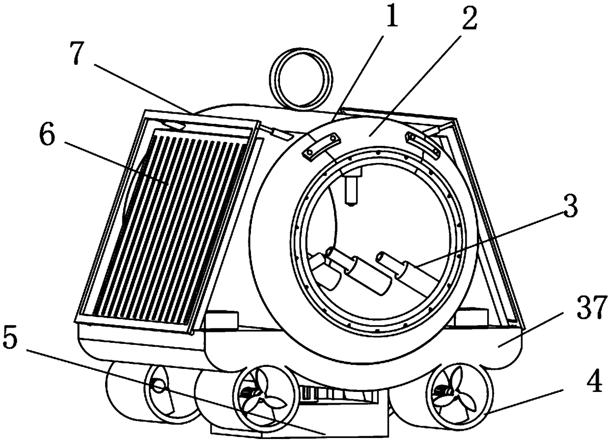
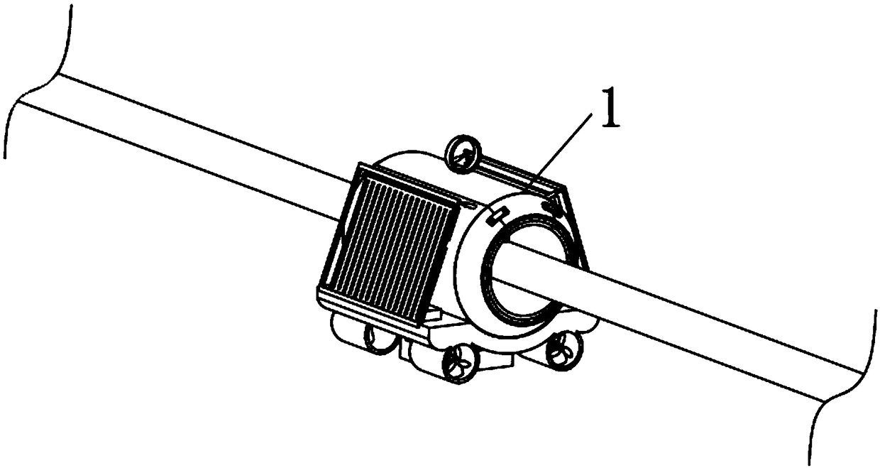
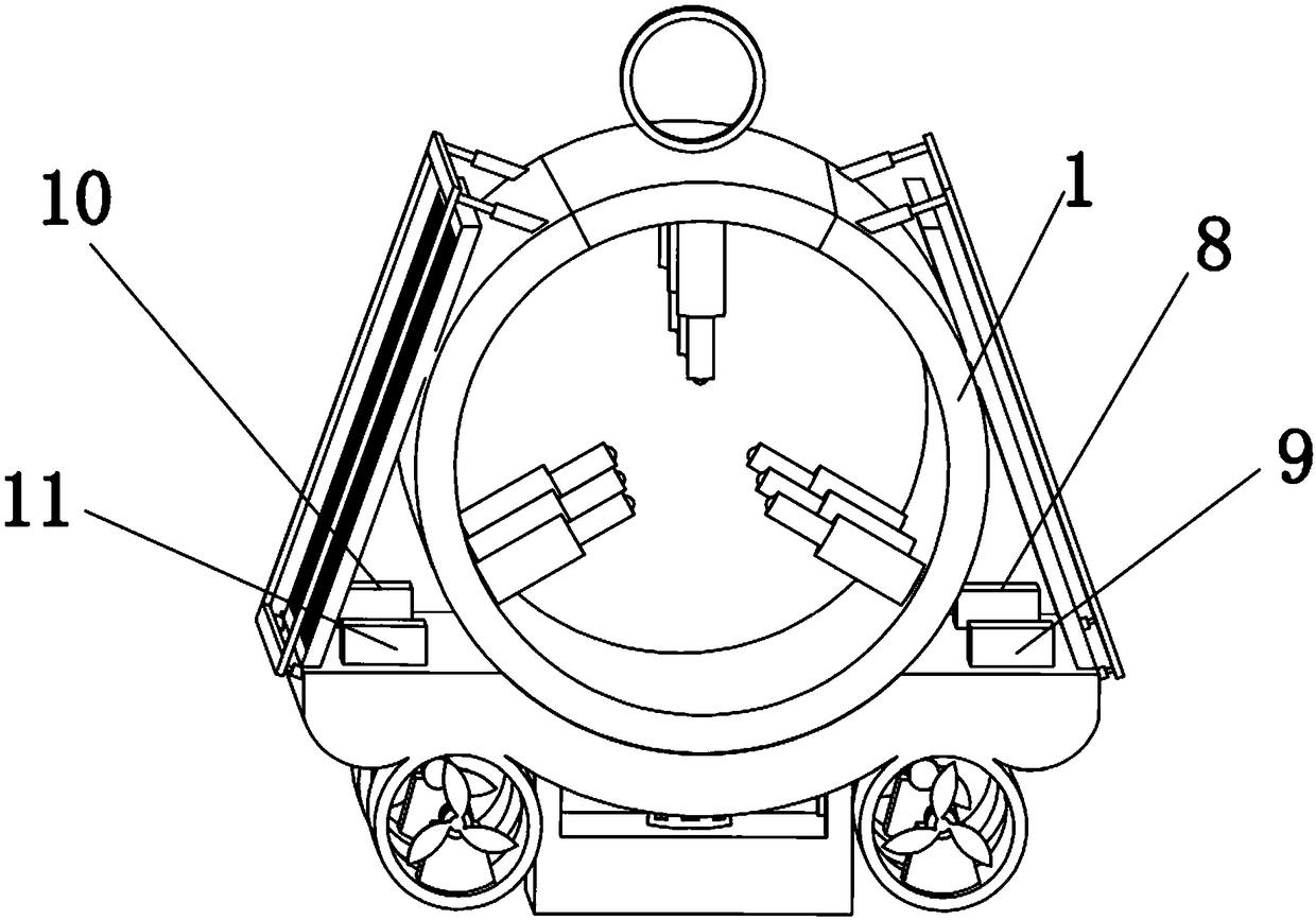
[0062] Embodiment one please refer to Figure 1-3 , a GPS-based line regular inspection equipment, including a cylinder 1, a snow removal device 2, a clamping device 3, a drive device 4, a weight reduction device 5, a solar panel 6 and a protection device 7, characterized in that: Both ends of the cylinder body 1 are symmetrically fixed with snow removal devices 2, and the cylinder body 1 is provided with clamping devices 3, and there are nine clamping devices 3, and every three are evenly distributed on the cylinder body in a ring. 1, and three rows are equidistantly arranged, the bottom of the cylinder 1 is fixed with a base 37, and the four corners of the bottom of the base 37 are respectively fixed with a driving device 4, and the driving device 4 at one end of the base 37 is connected to the The driving device 4 located at the other end of the base 37 faces oppositely, and the weight reducing device 5 is fixed at the center of the bottom of the base 37, and the solar cell...

Embodiment 2

[0063] Embodiment 2 Please refer to Figure 4 , the snow removal device 2 includes an outer cover 28, an inner cover 29 and a hot blower 30, the outer cover 28 and the inner cover 29 are fixed on the end of the cylinder body 1, and the outer cover 28 is sleeved on the outside of the inner cover 29, the described A heat blower 30 is fixedly connected to the inner cover 29 .

Embodiment 3

[0064] Embodiment three please refer to Figure 5 , 6, the clamping device 3 includes a sliding cylinder 12, an electromagnet plate 13, a first spring 14, a baffle plate 15, a sliding rod 16 and a ball 17, the sliding cylinder 12 is fixed on the inner wall of the cylinder body 1, and the sliding cylinder 12 The inner bottom is fixed with an electromagnet plate 13, one side of the electromagnet plate 13 is fixedly connected to one end of the first spring 14, and the other end of the first spring 14 is fixedly connected to the baffle plate 15, and the baffle plate 15 is connected with the sliding cylinder 12 is slidingly fitted, the side of the baffle plate 15 away from the first spring 14 is fixedly connected to one end of the sliding rod 16, and the sliding rod 16 passes through the sliding tube 12, and the other end of the sliding rod 16 is movably embedded with a ball 17.


PUM


Abstract

The invention discloses circuit periodic inspection equipment based on a GPS. The circuit periodic inspection equipment based on the GPS comprises a barrel body, snow removal devices, nine clamping devices, driving devices, a weight losing device, a solar cell panel and a protective device. The snow removal devices are symmetrically fixed at the two ends of the barrel body, the nine clamping devices are arranged in the barrel body, every three clamping devices are annularly and uniformly distributed on the inner wall of the barrel body, and the clamping devices are arranged in three rows of equidistantly. A base is fixed at the bottom of the barrel body, the driving devices are fixed at four corners of the bottom of the base correspondingly, and the orientation of the driving devices located at one end of the base is opposite to the orientation of the driving devices located at the other end of the base. The circuit periodic inspection equipment based on the GPS has high routing inspection speed and high efficiency and can inspect faults when the tiny faults appear in high-tension circuits, preventive measures are taken, power consumption is low, solar power supply is adopted, precision localization is achieved through the GPS after the faults are inspected, and rapid overhauling is achieved.

Description

technical field [0001] The invention relates to the technical field of high-voltage line fault detection, in particular to a GPS-based line regular inspection device. Background technique [0002] High-voltage lines usually refer to transmission lines that transmit voltages above 10kV (including 10kV). According to GB / T 2900.50-2008, definition 2.1, high voltage usually does not include 1000V. The voltage levels of high-voltage transmission lines in China are generally divided into: 35kV, 110kV, 220kV, 330kV, 500kV, 750kV, etc. [0003] High-voltage overhead transmission lines generally use steel-cored aluminum stranded wires. Under the combined action of huge variable tension, bending stress caused by vibration, and long-term fatigue caused by rapid changes in temperature, the material of the transmission line will become brittle. It will cause surface damage under the ground, which will inevitably lead to cracks and broken strands of high-voltage overhead transmission lin...

Claims


Application Information

Patent Timeline
Patent Type & Authority Applications(China)
IPC IPC(8): G01R31/08G01R31/02G01S19/14H02G1/02H02G7/16
CPCG01R31/085G01R31/50G01S19/14H02G1/02H02G7/16
Inventor 不公告发明人
Owner 南昌保莱科技有限公司
Why Eureka
Try Eureka