Frequency device compensation method, device and system and computer readable storage medium

A frequency device and frequency compensation technology, applied in the field of systems and computer-readable storage media, frequency device compensation methods, and devices, can solve the problems of missing predictor variables, high cost, and low temperature resolution

Pending Publication Date: 2019-01-15
ZTE CORP
View PDF8 Cites 5 Cited by
  • Summary
  • Abstract
  • Description
  • Claims
  • Application Information

AI Technical Summary

Problems solved by technology

There are two main reasons for the shortcomings of the existing technology: first, the temperature resolution is not high and the cost is high; second, other environmental factors cannot be compensated by temperature or time data, that is, the problem of missing predictor variables
The temperature predictor usually uses a temperature sensor chip to collect data. At present, the high-precision temperature sensor on the market has a resolution of 0.01 degrees, which costs about 3 US dollars, and the cost is high.
In addition, the fluctuation of the working power supply, or the frequency fluctuation caused by external influences such as vibration and shock, the commonly used temperature variables cannot be compensated

Method used


Image

  • Frequency device compensation method, device and system and computer readable storage medium
  • Frequency device compensation method, device and system and computer readable storage medium
  • Frequency device compensation method, device and system and computer readable storage medium

Examples


Embodiment 1

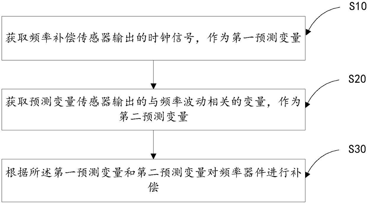
[0053] like figure 1 As shown, in this embodiment, a frequency device compensation method includes:

[0054] S10. Obtain the clock signal output by the frequency compensation sensor as the first predictor variable;

[0055] S20. Obtain a variable related to frequency fluctuation output by the predictive variable sensor as a second predictive variable;

[0056] S30. Compensate the frequency device according to the first predictor variable and the second predictor variable.

[0057] In this embodiment, the accuracy and stability of frequency compensation are improved by using a frequency sensor instead of a temperature sensor and adding predictive variables related to frequency fluctuations.

[0058] In this embodiment, the predicted variable is a variable related to the frequency fluctuation of the frequency device. The selection of the predicted variable and the accuracy of the predicted variable directly affect the compensation effect of the frequency device. Since the freq...

Embodiment 2

[0079] like Image 6 Shown is a specific structural diagram of frequency device compensation, including a power supply circuit 41, a current detection resistor 51, a MEMS oscillator 52 (microelectromechanical system, Microelectromechanical System), a digital phase-locked loop 43, MCU / CPU45, TCXO34, current The detection chip 54, the voltage detection chip 55 and the reference clock 44 are composed.

[0080] In this embodiment, the frequency component to be compensated is a TCXO 53 , and the frequency compensation sensor is a MEMS oscillator 52 . The two are placed as close as possible and share the power supply as much as possible, so as to increase the correlation of the frequency offset of the output clock signals 56 and 57 . The current detection resistor 51 and the current detection chip 54 complete the current detection function. The current detection chip 54 integrates an ADC circuit inside, converts the detected current into a digital signal and sends it to the MCU / CP...

Embodiment 3

[0082] like Figure 7 As shown, it is a specific structural diagram of frequency device compensation, including device package 60, frequency device XO61, frequency compensation sensor VCO62 (Voltage Controlled Oscillator, voltage controlled oscillator), power supply voltage VCC63, ground GND64, frequency device output clock 65 1. Frequency compensation sensor output clock 66. All parts form a new frequency device, which outputs two clock signals. The clock 65 is used as the clock of the common frequency device, and the clock 66 is used as a predictor variable. The power supply voltage VCC63 is respectively supplied to XO61 and VCO62, sharing the power supply so that power fluctuations can be transmitted to the clock frequencies of the output clock 65 and clock 66 of XO61 and VCO62, improving the compensation effect. The ground GND64 is connected to the ground of XO61 and VCO62. Putting the frequency compensation sensor VCO62 and the frequency device XO61 together can accura...


PUM


Abstract

The invention discloses a frequency device compensation method, device and system and a computer readable storage medium, and belongs to the technical field of communication. The method comprises acquiring a clock signal output by a frequency compensation sensor as a first predictive variable; acquiring a variable output by a predictive variable sensor and related to frequency fluctuation as a second predictive variable; compensating a frequency device according to the first predictive variable and the second predictive variable. By replacing a temperature sensor by a frequency sensor, and providing the predictive variable associated with the frequency fluctuation, the method improves the accuracy and stability of frequency compensation.

Description

technical field [0001] The present invention relates to the field of communication technology, in particular to a frequency device compensation method, device, system and computer-readable storage medium. Background technique [0002] Almost all electronic equipment, communication equipment, and automatic control equipment need a clock to ensure the normal operation of the system. The clock signals of these equipment basically come from frequency devices. In order to improve the accuracy of the clock, some systems use a phase-locked loop to track an external reference clock. The system has different requirements on the stability of the clock, and different levels of frequency devices and external reference clocks will be selected. Changes in the external environment will affect the stability of the frequency device, resulting in clock instability; the loss of the reference source will also lead to a decline in clock performance. When the reference clock is lost, or for a pe...

Claims


Application Information

Patent Timeline
Patent Type & Authority Applications(China)
IPC IPC(8): H03B5/32H03B5/04H03L7/085
CPCH03B5/04H03B5/32H03L7/085H03L7/093H03L7/087H03L1/00
Inventor 穆海明
Owner ZTE CORP
Why Eureka
Try Eureka