
High-altitude pruning device

A technology of pruning and driving device, applied in cutting tools, cutting equipment, gardening, etc., can solve the problems of time-consuming, labor-intensive, inconvenient, etc., and achieve the effect of accurate position, convenient operation, and stability.

Active Publication Date: 2019-01-18
CHANGZHOU COLLEGE OF INFORMATION TECH
View PDF9 Cites 0 Cited by
  • Summary
  • Abstract
  • Description
  • Claims
  • Application Information

AI Technical Summary

Problems solved by technology

There are also some pruning tools in the form of telescopic rods to solve the problem of pruning high branches, but these pruning tools are relatively inconvenient to use, and the branches are not easy to be cut when the branches shake during the cutting operation, which is time-consuming and laborious

Method used


Image

  • High-altitude pruning device
  • High-altitude pruning device
  • High-altitude pruning device

Examples


Embodiment 1

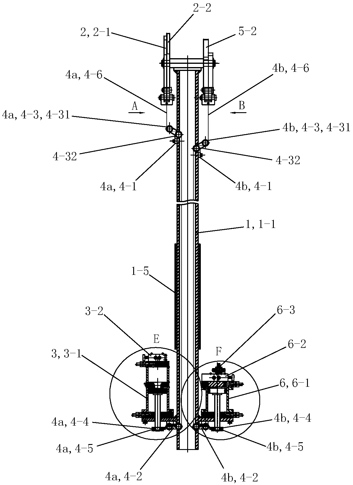
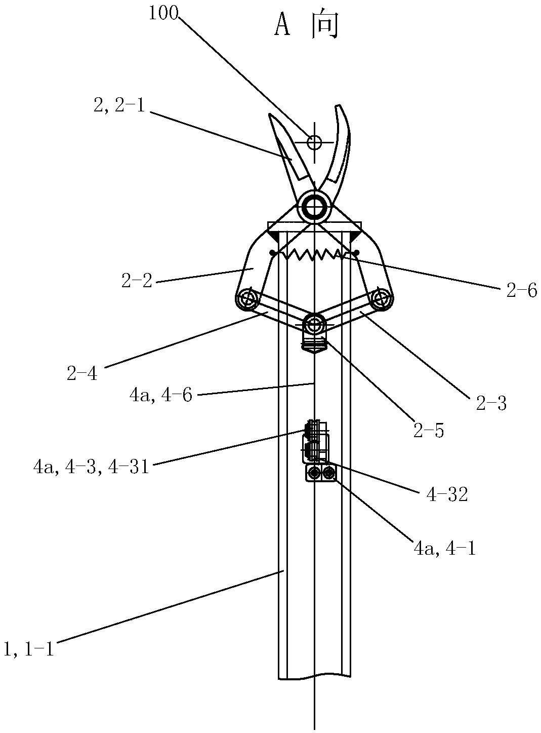
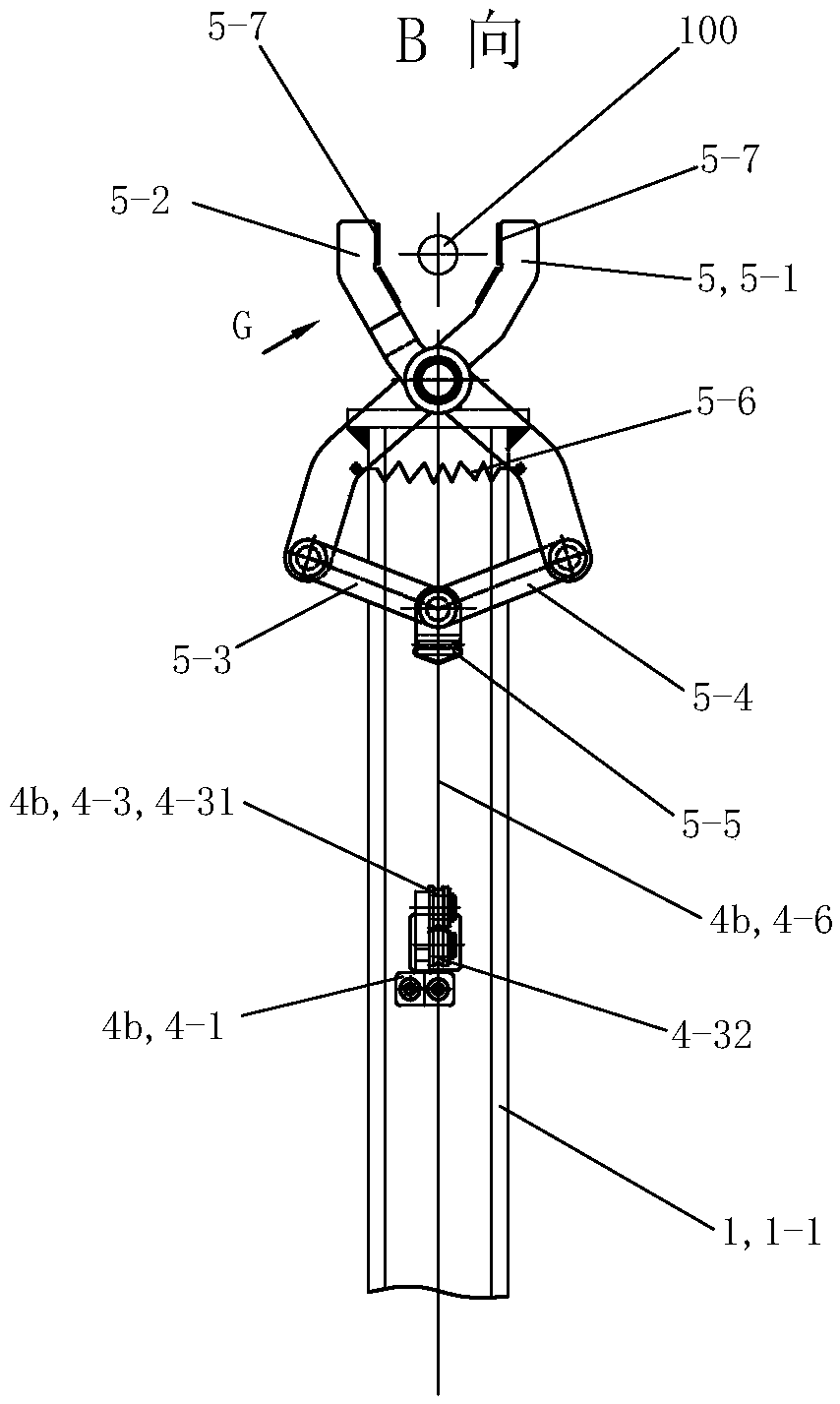
[0067] See Figure 1 to Figure 10 , The high-altitude pruning device of the present invention includes a brace assembly 1 , a cutting assembly 2 , a first driving device 3 , a transmission assembly 4 , a clamping assembly 5 and a second driving device 6 .

[0068] See Figure 1 to Figure 3 and Figure 11 to Figure 14 , The strut assembly 1 includes a strut 1-1, a lower mounting seat 1-2, an upper mounting plate 1-3, an upper mounting shaft 1-4 and a grip sleeve 1-5. The strut 1-1 is made of hard aluminum alloy, and the strut 1-1 is hollow tubular. The upper mounting plate 1-3 is welded and fixedly arranged on the upper end of the strut 1-1. The upper mounting shaft 1-4 is fixedly welded and fixed on the upper mounting plate 1-3 along the radial direction of the strut 1-1, and is arranged along the left and right directions. The lower mounting seat 1-2 is a circular mounting plate, and the center is provided with an installation through hole that runs through it up and down...

Embodiment 2

[0085] The rest of this embodiment is the same as that of Embodiment 1, the difference being that: the strut assembly 1 is also provided with strap rings 1-6 and straps. The strap suspension ring 1-6 is fixedly arranged on the front upper side of the lower mounting base 1-2. When in use, the strap suspension rings 1-6 are fixedly connected with the strap, and the operator carries the strap on his back, which helps to reduce the labor intensity of the operator, and is convenient for weaker operators to hold alone, making it more convenient to use.

Embodiment 3

[0087] The rest of this embodiment is the same as Embodiment 1, except that the second driving device does not include the one-way speed regulating valve 6-3. The fourth interface 6-24 is in airtight communication with the gas source through a corresponding pipeline. The first interface 6-21 of the second two-position five-way manual reversing valve 6-2 is airtightly communicated with the air inlet 6-11 on the second cylinder of the second cylinder 6-1 through a corresponding pipeline. The second interface 6-22 of the second two-position five-way manual reversing valve 6-2 is airtightly communicated with the lower air inlet 6-12 of the second cylinder 6-1 through a corresponding pipeline.


PUM


Abstract

The invention discloses a high-altitude pruning device, which is characterized by comprises a stay rod component, a shearing component, a first driving device, a transmission component, a clamping component and a second driving device. Two groups of transmission components have the same structure, and the two groups of transmission components are divided into a left transmission component and a right transmission component according to the difference of the left position and the right position of the transmission components. The strut assembly includes a strut and a lower mounting seat. And the lower mounting seat is welded and fixed on the lower part of the brace rod. The first driving device is fixedly arranged on the left part of the lower mounting seat. And the first driving device drives the front cutter bar and the rear cutter bar of the shearing assembly to carry out shearing operation through the left side transmission assembly. And the second driving device is fixedly arrangedon the right part of the lower mounting seat. And the front clamping arm and the rear clamping arm of the clamping assembly are driven by the second driving device through the right side transmissionassembly to carry out clamping positioning operation.

Description

technical field [0001] The invention relates to the technical field of branch pruning tools, in particular to a high-altitude pruning device for pruning high branches. Background technique [0002] A tree is a tall woody plant, represented by "branches" and "stalks" and "leaves", that can live for decades. Arbors are generally referred to as trees, with a distinct upright trunk, generally tall plants, and branches that are higher from the ground to form a canopy. Trees and green plants continuously carry out photosynthesis, consume carbon dioxide and produce fresh oxygen; more than 60% of the oxygen in the air comes from trees and green plants on land, so people compare trees and green plants to "manufacturing plants of oxygen", " factory of fresh air". [0003] Planting trees, planting grass and flowers in the city, covering or decorating a certain ground or space, on the one hand, it plays a role of aesthetic decoration, and on the other hand, it is used to improve the q...

Claims


Application Information

Patent Timeline
IPC IPC(8): A01G3/025
CPCA01G3/0255
Inventor 苏沛群苏梁张红卫
Owner CHANGZHOU COLLEGE OF INFORMATION TECH
Learn More