
Rebar hoop bending device

A steel bar bending hoop and bending pin technology, applied in the field of construction machinery, can solve the problems of high labor intensity, low production efficiency, high defective rate, etc., and achieve the effect of high labor intensity and simple structure

Active Publication Date: 2019-01-18
YANGTZE UNIVERSITY
View PDF6 Cites 3 Cited by
  • Summary
  • Abstract
  • Description
  • Claims
  • Application Information

AI Technical Summary

Problems solved by technology

[0003] The object of the present invention is to provide a steel bar bending device with simple structure and convenient use to solve the problems of high labor intensity, high defective rate and low production efficiency in the existing method of bending hoops

Method used


Image

  • Rebar hoop bending device
  • Rebar hoop bending device
  • Rebar hoop bending device

Examples


Embodiment Construction

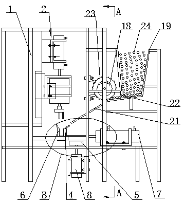
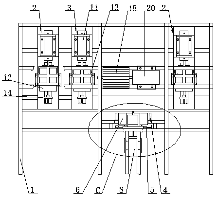
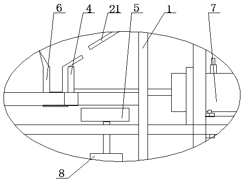
[0024] The steel hoop bending device is composed of a frame 1, a feeder, a bender A2, a bender B3, a bending pin 4, an unloading ramp 5 and a bending puller 6 (see the attached figure 1 ).

[0025] The feeder is equipped with on the frame 1; The feeder is made of feeding dial 18, material storage box 19, drive motor 20 and feeder plate 21; The material storage box 19 communicates with the feeding plate 21 through the material outlet 22; The purpose of arranging the storage box 19 and the feeding plate 21 in this way is to make the workpiece 24 (steel bar) to be bent in the storage box 19 automatically roll down to the feeding plate through the discharge port 22 under the action of its own gravity. 21 in.

[0026] The size of the discharge opening 22 is greater than one time workpiece 24 diameter and less than twice the workpiece 24 diameter; Plate 21, so that the output workpieces 24 are closely arranged on the feeding plate 21, so that the feeding dial 18 is convenient for...


PUM


Abstract

The invention relates to a rebar loop bending device, and belongs to the technical field of construction machinery. The rebar hoop bending device is composed of a machine frame, a feeder, benders A, benders B, bending gear pins, unloading inclined plates and bending pull heads. The feeder is installed on the machine frame, and the portion, below one side of the feeder, of the machine frame is spacedly provided with the bending gear pins; the bending pull heads are installed between the two bending gear pins through bending cylinders; the lower portions of the bending pull heads are provided with the unloading inclined plates through unloading cylinders, the portions, above one sides of the bending gear pins, of the machine frame are spacedly provided with the benders B and benders A, and the portions, above the other sides of the bending gear pins, of the machine frame are provided with the benders A. The rebar bending hoop device is simple in structure, can mechanically complete rebarbending actions, solves the problems that an existing rebar hoop bending means has large labor intensity, high in defective rate and low in production efficiency, and meets the requirements for enterprise production and application.

Description

technical field [0001] The invention relates to a steel bar bending hoop device, which belongs to the technical field of construction machinery. Background technique [0002] The construction industry needs to use a large number of bent and formed hoops every day. At present, the forming of steel hoops is still done manually with the aid of instruments. A hoop needs to be bent at five places of the steel bar to form a complete hoop. The existing hoop forming method not only has the problem of slow speed and low efficiency, but also has high labor intensity and defective products. The problem of high rate; can not meet the needs of enterprise production and use. Therefore be necessary to develop a kind of tendon hoop forming machine, make it can complete the bending work of tendon hoop mechanized, to solve the above problems that existing bending hoop mode exists. Contents of the invention [0003] The object of the present invention is to provide a steel bar bending devi...

Claims


Application Information

Patent Timeline
Patent Type & Authority Applications(China)
IPC IPC(8): B21F1/00
CPCB21F1/004
Inventor 彭三河陈义厚杨友平周传喜
Owner YANGTZE UNIVERSITY
Learn More