A kind of rubber hose automatic cutting equipment and rubber hose automatic cutting process
What is Al technical title?
Al technical title is built by PatSnap Al team. It summarizes the technical point description of the patent document.
A rubber hose, automatic cutting technology, applied in metal processing and other directions, can solve problems such as scratches on the surface of the rubber hose, potential safety hazards, uneven cutting surface, etc., to eliminate adverse effects, eliminate safety hazards, and smooth the cutting surface. Effect
Active Publication Date: 2020-05-15
中金液压胶管股份有限公司
View PDF7 Cites 0 Cited by
Summary
Abstract
Description
Claims
Application Information
AI Technical Summary
This helps you quickly interpret patents by identifying the three key elements:
Problems solved by technology
Method used
Benefits of technology
Problems solved by technology
[0003] In order to make up for the deficiencies of the prior art, the present invention provides an automatic rubber hose cutting device and a rubber hose automatic cutting process. The present invention can solve the problems of high labor cost, low work efficiency, The cutting surface is uneven, there are potential safety hazards and it is easy to scratch the surface of the rubber hose. It can realize the function of automatic cutting of the rubber hose. It has the advantages of low labor cost, high work efficiency, flat cutting surface, and wide application range. Not easy to scratch the surface of the rubber hose, etc.
Method used
Image
Click on the blue label to locate the original text in one second.
Reading with bidirectional positioning of images and text.
Examples
Embodiment Construction
[0030] In order to make the technical means, creative features, goals and effects achieved by the present invention easy to understand, the present invention will be further described below in conjunction with specific illustrations.
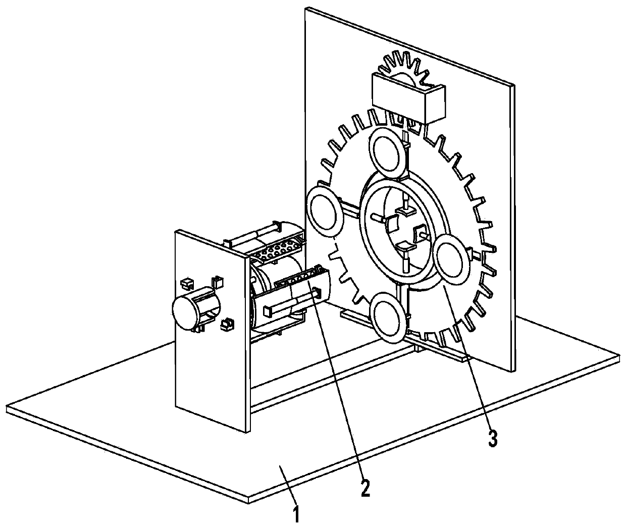
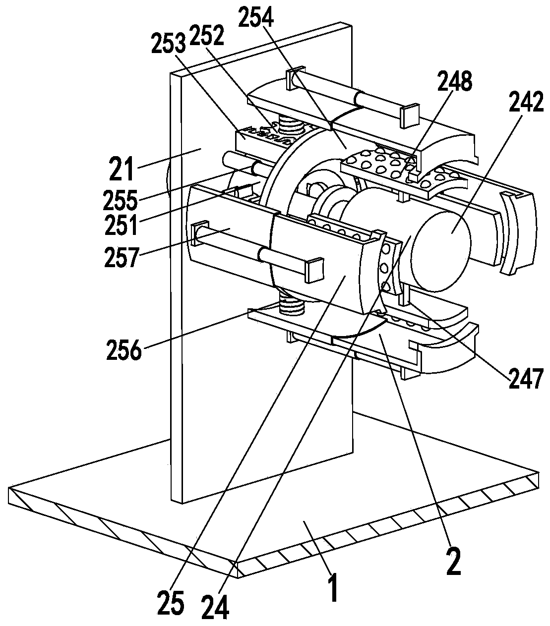
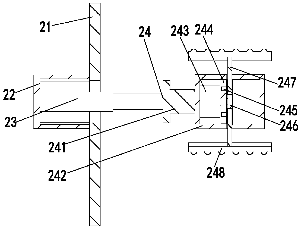
[0031] Such as Figure 1 to Figure 6 As shown, an automatic rubber hose cutting device includes a base plate 1, a support device 2 and a cutting device 3, and the support device 2 and the cutting device 3 are installed on the base plate 1 in turn from left to right; wherein:
[0032] The supporting device 2 comprises a fixed plate 21, a fixed frame 22, a moving cylinder 23, an inner wall support mechanism 24 and an outer wall support mechanism 25, the fixed plate 21 is installed on the base plate 1, and the fixed plate 21 side walls are provided with circular holes, circular holes Adjustment holes are evenly arranged on the outer side along its circumferential direction, and a fixed frame 22 is arranged on the left side of the circular hole. The...
PUM
Abstract
The invention relates to automatic rubber hose cutting equipment and an automatic rubber hose cutting technology. The automatic rubber hose cutting equipment comprises a bottom plate, a supporting device and a cutting device, and the supporting device and the cutting device are sequentially installed on the bottom plate from left to right; the supporting device comprises a fixing plate, a fixed frame, a movable air cylinder, an inner wall supporting mechanism and an outer wall supporting mechanism; the cutting device comprises a linear guide rail, an electric sliding block, a working plate, aworking gear, a driving gear, a driving motor, a rotating ring, a rotating gear, a rotating motor, a supporting air cylinder, a supporting plate, a rotating rod, a sliding frame, a mounting frame, a cutting motor and a cutting blade. The invention further provides a using method of the automatic rubber hose cutting equipment. The equipment and the technology can solve the problems that in an existing rubber hose cutting process, the labor cost is high, the working efficiency is low, the cutting surface is not smooth, safety hidden hazards exist and the surface of a rubber hose is easily scratched, and the function of automatically cutting the rubber hose can be achieved.
Description
technical field [0001] The invention relates to the field of rubber hose processing equipment, in particular to an automatic rubber hose cutting equipment and a rubber hose automatic cutting process. Background technique [0002] After the same production and processing, the rubber hose is often longer in length. Before use, the rubber hose needs to be cut to an appropriate length according to the actual situation. At present, the rubber hose is usually cut manually. When cutting, the rubber hose needs to be fixed on the existing equipment, or the rubber hose is pulled and fixed by the staff, and then another staff uses the knife and scale Cutting the rubber hose with a ruler, the labor cost is high, the work efficiency is low, and due to the instability of manual operation, the accuracy of the cutting length and the smoothness of the cutting surface cannot be guaranteed, and it is easy to cause scratches on the surface of the rubber hose In addition, when the staff is usin...
Claims
Application Information
Patent Timeline
Application Date:The date an application was filed.
Publication Date:The date a patent or application was officially published.
First Publication Date:The earliest publication date of a patent with the same application number.
Issue Date:Publication date of the patent grant document.
PCT Entry Date:The Entry date of PCT National Phase.
Estimated Expiry Date:The statutory expiry date of a patent right according to the Patent Law, and it is the longest term of protection that the patent right can achieve without the termination of the patent right due to other reasons(Term extension factor has been taken into account ).
Invalid Date:Actual expiry date is based on effective date or publication date of legal transaction data of invalid patent.