Pneumatic slurry stirring system and slurry stirring method thereof
A mixing system and mud technology, applied in cement mixing devices, chemical instruments and methods, clay preparation devices, etc., can solve the problems of low mixing cost and low mixing energy consumption
- Summary
- Abstract
- Description
- Claims
- Application Information
AI Technical Summary
Problems solved by technology
Method used
Image
Examples
Embodiment 1
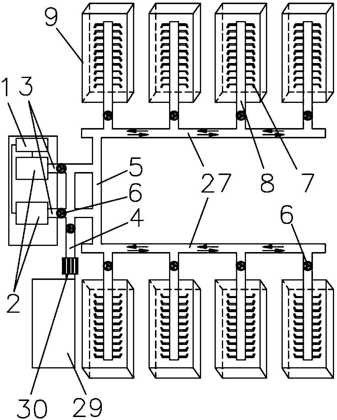
[0041] Example 1, such as Figure 1-8 Shown:
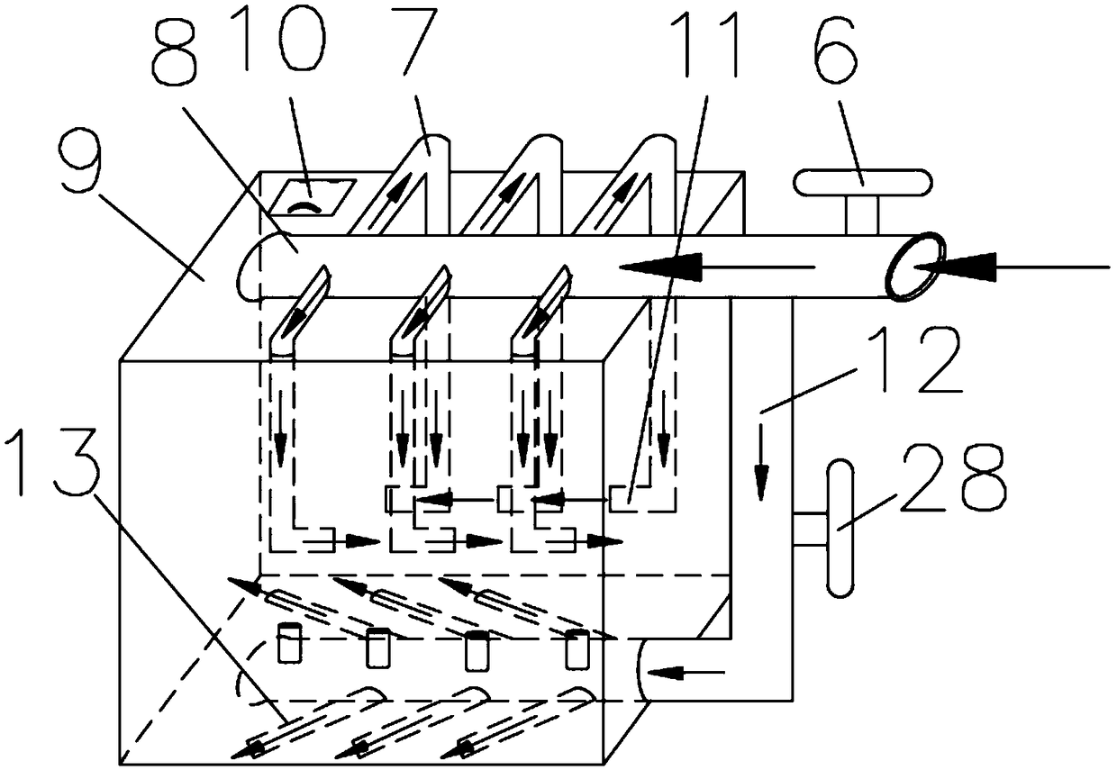
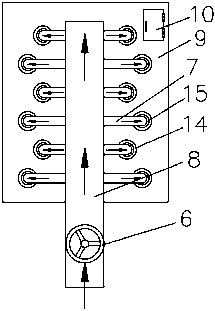
[0042]A pneumatic mud mixing system, comprising a power distribution cabinet 1, a number of fans 2 and a number of mud tanks 9; the position of the air outlet of the fan 2 is fixedly connected with an air outlet pipe 3, and each of the air outlet pipes 3 is equipped with There is a switching valve 6, the right end of the switching valve 6 of the air outlet pipe 3 is provided with a water inlet pipe 4 vertically connected with the air outlet pipe 3, the outer end of the water inlet pipe 4 is connected to the water pump 30, and the end of the water inlet pipe 4 close to the water pump 30 is installed together There is a water valve switch 28; the other end of the water pump 30 is connected to the water tank 29; the outer end of the air outlet pipe 3 is airtightly connected to the horizontal pipe 5, and the two ends of the horizontal pipe 5 are respectively airtightly connected to the main pipe 27, and the outside of the main pipe 27...
Embodiment 2
[0063] Example 2, such as image 3 Shown:
[0064] The branch pipe 7 of the present application is an L-shaped structure, which is formed by fixedly connecting a horizontal branch pipe 35 and a vertical branch pipe 36; the lengths of the horizontal branch pipes 35 on both sides of the branch pipe 8 can be set to different lengths. Or the horizontal branch pipe 35 is designed according to different lengths to form different shapes. For example: the horizontal branch pipes 35 on both sides of the branch pipe 8 are arranged according to the structure of long-short-long-short..., and then a vertical branch pipe 36 is fixedly connected to the lower side of the outer end of each horizontal branch pipe 35 , the exhaust pipe at the lower end of the vertical branch pipe 36 is uniformly arranged in a counterclockwise or clockwise direction, so that the mud can be swirled and stirred. Perhaps the horizontal branch pipe 35 is selected and designed according to the length, so that after ...
Embodiment 3
[0065] Example 3, such as figure 2 Shown:
[0066] At the lower end 36 of the vertical pipe, the exhaust pipe 11 may not be provided, and the pipeline that does not have the exhaust pipe 11 at the lower end is directly used to connect the three-way valve 32, so that the bottom of the mud tank 9 is filled with high-speed gas by the high-speed air flow, and the bottom is drawn by the high-speed gas. The sedimentation mud is tumbling upwards to realize the up and down floating and tumbling of the mud to achieve the effect of mud stirring. In this embodiment, the density of the mud is 1.05-3.0 kg / m3. When the density of the mud is 2 kg / m3, the Roots Blower 2 with the model ZXSR150 can be used to meet the requirements.
PUM
| Property | Measurement | Unit |
|---|---|---|
| density | aaaaa | aaaaa |
Abstract
Description
Claims
Application Information
 - R&D
- Intellectual Property
- Life Sciences
- Materials
- Tech Scout
- Unparalleled Data Quality
- Higher Quality Content
- 60% Fewer Hallucinations
Browse by: Latest US Patents, China's latest patents, Technical Efficacy Thesaurus, Application Domain, Technology Topic, Popular Technical Reports.
© 2025 PatSnap. All rights reserved.Legal|Privacy policy|Modern Slavery Act Transparency Statement|Sitemap|About US| Contact US: help@patsnap.com


