Bookbinding machine

A binding machine and fuselage technology, applied in binding and other directions, can solve problems such as improper operation, low efficiency, and limb injuries

Inactive Publication Date: 2019-01-18
三门县利成电子科技有限公司
View PDF0 Cites 9 Cited by
  • Summary
  • Abstract
  • Description
  • Claims
  • Application Information

AI Technical Summary

Problems solved by technology

[0002] The traditional riveting tube binding machine needs to manually take out the binding paper after punching the hole, then take out the riveting tube from the inside of the machine and manually insert it into the hole, and then align the binding hole with the riveting tube ...

Method used


Image

  • Bookbinding machine
  • Bookbinding machine
  • Bookbinding machine

Examples


Embodiment Construction

[0015] All features disclosed in this specification, or steps in all methods or processes disclosed, may be combined in any manner, except for mutually exclusive features and / or steps.

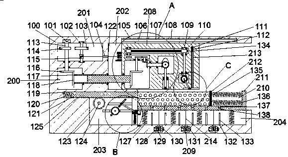
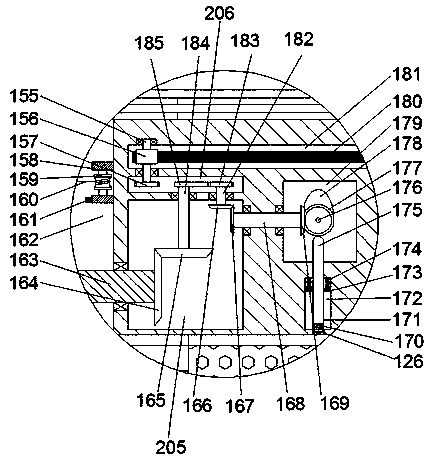
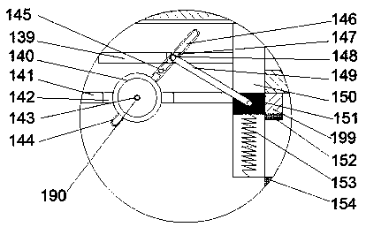
[0016] Such as Figure 1-Figure 4As shown, a binding machine of the present invention includes a body 100 and a first cavity 200 disposed in the left end wall of the body 100, and a second cavity 201 is disposed in the top wall of the first cavity 200 A first rotating shaft 113 is rotatably arranged between the second cavity 201 and the first cavity 200, and the top end of the first rotating shaft 113 in the second cavity 201 is fixedly arranged on the first rotating shaft 113. The first motor 101 in the top wall of the two cavities 201 is power-connected, the outer surface of the first rotating shaft 113 in the second cavity 201 is fixedly provided with a first sector gear 114, and the first sector gear 114 in the first cavity 200 is The end of the first rotating shaft 113 is fixedly provide...


PUM


Abstract

The invention discloses a bookbinding machine which comprises a machine body and a first cavity formed in the end face of the left side of the machine body. A second cavity is formed inside the top wall of the first cavity. A first rotating shaft is rotationally arranged between the second cavity and the first cavity. The tail end of the top of the first rotating shaft inside the second cavity isin power connection with a first motor fixedly arranged inside the top wall of the second cavity. The machine is easy and convenient to operate, by means of the mechanical structure, the complete flowscheme for semi-automatic rivet tube bookbinding is achieved, meanwhile, mechanical parts are simple, the requirement for the function cost is low, equipment main mechanisms are matched compactly, the equipment practicability is high, meanwhile, kinetic energy conversion is adjusted by means of the mechanical structure, and the rivet tube bookbinding efficiency is improved.

Description

technical field [0001] The invention relates to the field of mechanical production and manufacturing, in particular to a binding machine. Background technique [0002] The traditional riveting tube binding machine needs to manually take out the binding paper after punching the hole, then take out the riveting tube from the inside of the machine and manually insert it into the hole, and then align the binding hole with the riveting tube with the heating tube for heating and extrusion molding. Such operations are cumbersome, the degree of automation is not high, and the efficiency is extremely low. It is easy to cause limb injuries due to improper operation. There is an urgent need for a device to solve such problems. Contents of the invention [0003] The technical problem to be solved by the present invention is to provide a binding machine, which can solve the above-mentioned problems in the prior art. [0004] The present invention is achieved through the following tech...

Claims


Application Information

Patent Timeline
IPC IPC(8): B42B5/00B42B5/02
CPCB42B5/00B42B5/02
Inventor 余聪
Owner 三门县利成电子科技有限公司
Why Eureka
Try Eureka