A filling and capping machine and a filling and capping method
A capping machine and filling technology, which is applied to bottling machines, packaging, screw caps, etc., can solve the problems of complex overall equipment structure, large space occupation, unfavorable factory layout, etc., and achieve a reasonable overall layout and less space occupation , the effect of improving the pass rate
- Summary
- Abstract
- Description
- Claims
- Application Information
AI Technical Summary
Problems solved by technology
Method used
Image

Examples
Embodiment 1
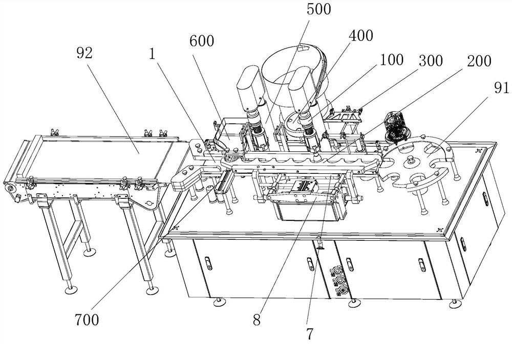
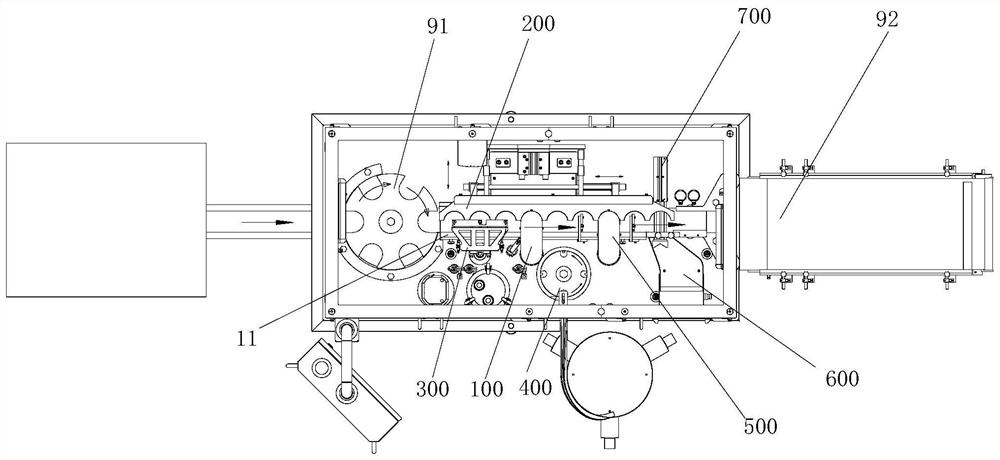
[0043] Figure 1 to Figure 2 An embodiment of the filling and capping machine of the present invention is shown. The filling and capping machine of this embodiment includes a bottle feeding track 1, a bottle feeding part 91 arranged upstream of the bottle feeding track 1, and a bottle feeding part 91 located on the bottle feeding track. 1 downstream of the bottle output part 92, the both sides of the bottle delivery track 1 are respectively provided with a bottle delivery fence 11 and an intermittent bottle delivery device 200, and the intermittent bottle delivery device 200 is provided with a positioning member 7 for positioning the medicine bottle below the intermittent bottle delivery device 200. Part 7 is connected with the positioning drive mechanism 8 that is used to drive positioning member 7 to move back and forth along the conveying direction of vertical bottle conveying track 1, and along the conveying direction of conveying bottle conveying track 1, the bottle convey...
Embodiment 2
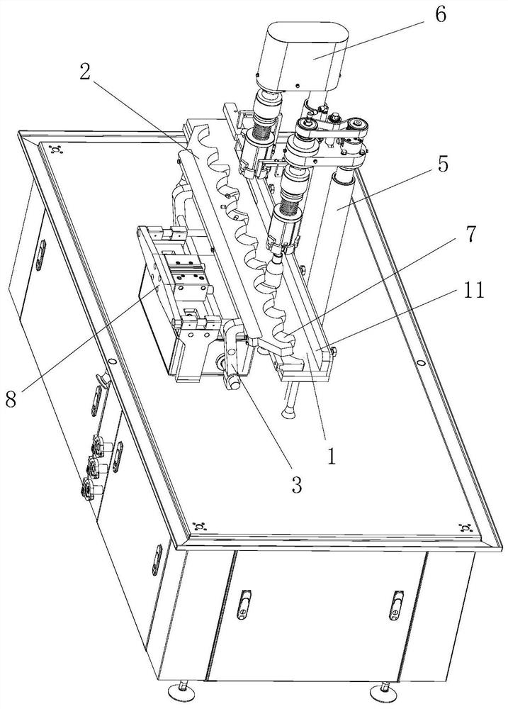
[0046] Figure 3 to Figure 7 An embodiment of the intermittent bottle conveying device 200 of the present invention is shown. As a preferred technical solution, in this embodiment, the intermittent bottle conveying device 200 includes a bottle dial 2, a bottle for driving the bottle dial 2 to turn up and down. Turn over drive mechanism 3, and the bottle turn drive mechanism 4 that is used to drive bottle turn part 2 and turn over drive mechanism 3 to reciprocate along the conveying direction of bottle conveying track 1 as a whole, and turn bottle part 2 is provided with a plurality of turn bottle parts 21, Each bottle pulling part 21 is evenly arranged along the conveying direction of the bottle conveying track 1 , and a plurality of positioning parts 71 are arranged on the positioning member 7 , and each positioning part 71 is arranged in one-to-one correspondence with each bottle pulling part 21 . Wherein, the bottle pulling part 21 preferably adopts a groove structure, of c...
Embodiment 3
[0056] Figure 8 to Figure 10 An embodiment of the pre-capping device 100 of the present invention is shown. In this embodiment, the pre-capping device 100 includes a cap removal shaft 104, a first rotation driving member 105, and a first rotating shaft for driving the cap removal shaft 104 to go up and down. Lifting drive mechanism 106, pre-rotating cap pneumatic gripper 101, pre-rotating cap rotating shaft 102 for driving pre-rotating cap pneumatic gripper 101 to rotate, and pre-rotating cap rotating shaft seat 103 for installing pre-rotating cap rotating shaft 102, taking the cap The lower end of the rotating shaft 104 is connected with the first rotating driving member 105 and the upper end is provided with a second rotating driving member 109. At least one set of lifting guide assembly is provided on the side of the rotating shaft 104 for removing the cap. , the second rotation driver 109 is connected to the pre-rotating cap rotating shaft 102 through the first transmission...
PUM
 Abstract
Description
Claims
Application Information
 - R&D
- Intellectual Property
- Life Sciences
- Materials
- Tech Scout
- Unparalleled Data Quality
- Higher Quality Content
- 60% Fewer Hallucinations
Browse by: Latest US Patents, China's latest patents, Technical Efficacy Thesaurus, Application Domain, Technology Topic, Popular Technical Reports.
© 2025 PatSnap. All rights reserved.Legal|Privacy policy|Modern Slavery Act Transparency Statement|Sitemap|About US| Contact US: help@patsnap.com