Pressure-accumulating dual-valve electronic fuel injector

An electronically controlled fuel injection and pressure accumulator technology, which is applied in the direction of machines/engines, fuel injection devices, engine components, etc., can solve the problems of fuel injectors not working normally, pressure fluctuations of pressurized electronically controlled fuel injectors, and adverse consequences And other issues

Inactive Publication Date: 2019-01-18
HARBIN ENG UNIV
View PDF4 Cites 1 Cited by
  • Summary
  • Abstract
  • Description
  • Claims
  • Application Information

AI Technical Summary

Problems solved by technology

The existing pressurized electronically controlled fuel injector can further pressurize the fuel in the common rail pipe. It has a fast response and can realize precise control of the fuel injection quantity, but there are also some shortcomings: the pressurized electronically controlled injector The fuel injector is easy to cause large pressure fluctuations during the fuel injection process, and the working mode is relatively single, especially for the fuel injector controlled by a single solenoid valve, once the solenoid valve fails, the entire fuel injector will not work normally , can easily cause adverse consequences, and the problem of poor work reliability has become the key to restricting the wider application of pressurized electronically controlled injectors

Method used


Image

  • Pressure-accumulating dual-valve electronic fuel injector
  • Pressure-accumulating dual-valve electronic fuel injector
  • Pressure-accumulating dual-valve electronic fuel injector

Examples


Embodiment Construction

[0021] The present invention is described in more detail below in conjunction with accompanying drawing example:

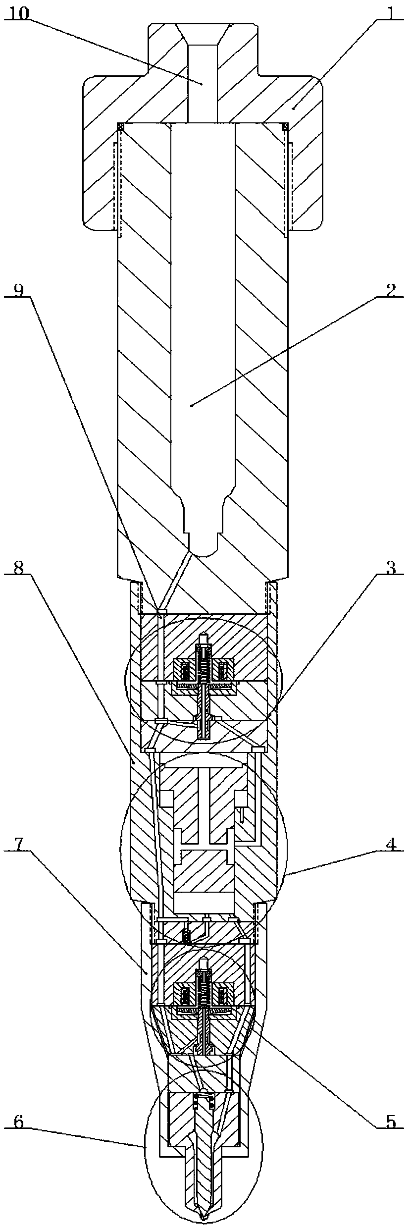
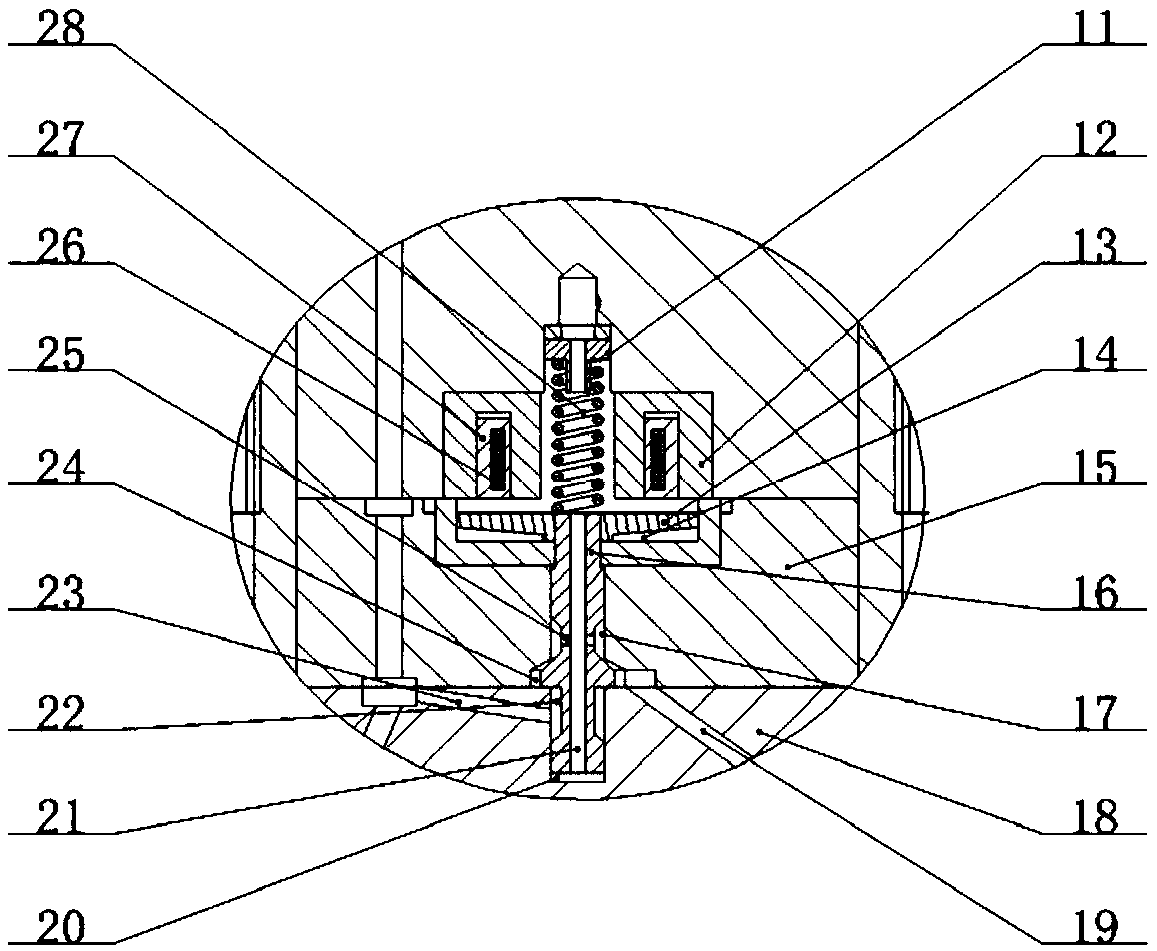
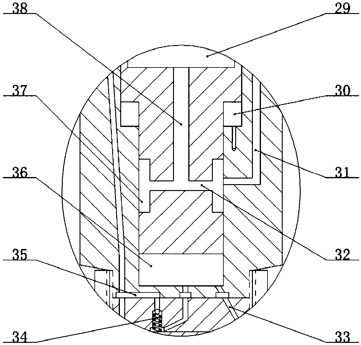
[0022] combine Figure 1-5 , the pressure accumulator double-valve electronically controlled fuel injector of the present invention comprises an injector head 1, a pressure accumulator chamber 2, a boost control valve 3, a boost piston 4, a fuel injection control valve 5, a nozzle 6, and a tight cap 7 and the fuel injector body 8, the fuel injector head 1 is installed on the fuel injector body 8, the fuel injector body 8 has a pressure accumulator chamber 2, the fuel injector head 1 has a main oil inlet hole 10, the main inlet The oil hole 10 communicates with the upper end of the pressure storage chamber 2, and the lower end of the pressure storage chamber 2 communicates with the main oil inlet passage 9. The boost control valve 3, the boost piston 4, the fuel injection control valve 5 and the nozzle 6 are installed in sequence from top to bottom. In the fuel in...


PUM


Abstract

It is an object of the present invention to provide a pressure-accumulating dual-valve electronic fuel injector. The pressure-accumulating dual-valve electronic fuel injector comprises a fuel injectorhead, a pressure-accumulating chamber wall, a pressurizing control valve, a pressurizing piston, a fuel injection control valve, a nozzle and a fuel injector body. The fuel injector body is providedtherein with a pressure accumulating chamber, which can reduce the pressure fluctuation in a fuel injection process, and is advantageous for the precise control of the fuel injection. The pressure-accumulating dual-valve electronic fuel injector can reduce the structural size of a common rail tube when used in a common rail fuel system, thereby reducing the material strength requirements of the common rail tube, prolonging the service life of the common rail tube and improving the space utilization ratio of the common rail tube. The pressure-accumulating dual-valve electronic fuel injector canwork in both non-pressurizing and pressurizing modes. In the non-pressurizing mode, the rail pressure injection is performed. In the pressurizing mode, the ultrahigh-pressure injection is performed,and the pressuring ratio can be flexibly adjusted, thereby achieving high reliability and a wide application range. The fuel injection control valve can stop the control chamber from replenishing thefuel during the fuel draining process, realizes micro dynamic oil return, improves the response speed of the needle valve, and improves the dynamic property and economical efficiency of a diesel engine.

Description

technical field [0001] The invention relates to a diesel engine, in particular to a diesel engine fuel system. Background technique [0002] As a highly flexible control fuel injection system, the high-pressure common rail system has become one of the main development directions of modern diesel engine technology with its remarkable advantages. The combination of electronic control technology and high-pressure common rail system makes the fuel injection system of the diesel engine independent For the work of the fuel supply system, with the increasingly stringent emission regulations and the continuous progress of the electronically controlled fuel injection technology of diesel engines, the improvement of the high-pressure common rail fuel injection system of diesel engines has attracted much attention. [0003] The electronically controlled fuel injector is the core component of the high-pressure common rail fuel injection system of the diesel engine. The effect of boosti...

Claims


Application Information

Patent Timeline
Patent Type & Authority Applications(China)
IPC IPC(8): F02M47/02F02M51/06F02M61/10F02M61/16F02M61/18F02M63/00
CPCF02M47/027F02M51/061F02M61/10F02M61/16F02M61/18F02M63/0017
Inventor 白云刘思伯兰奇范立云
Owner HARBIN ENG UNIV
Why Eureka
Try Eureka