
Wood drying device

A wood drying and rotating shaft technology, which is applied in wood drying, dry solid materials, dry cargo handling, etc., can solve problems affecting processing efficiency and labor costs, improve automation and practicability, improve efficiency, and facilitate installation and maintenance The effect of overhaul

Inactive Publication Date: 2019-01-18
SHAOXING XIHENG TECH CO LTD
View PDF0 Cites 0 Cited by
  • Summary
  • Abstract
  • Description
  • Claims
  • Application Information

AI Technical Summary

Problems solved by technology

[0002] With the development of society, the demand for wood products is increasing, so the requirements for wood processing are getting higher and higher. Drying the wood before wood processing can not only reduce the weight of the wood but also increase the strength of the wood. However, before the wood is dried, kiln stacking is required. At present, most of the kiln stacking is done by manpower, which greatly affects the processing efficiency and labor cost. Therefore, a new type of equipment is needed to solve this problem.

Method used


Image

  • Wood drying device
  • Wood drying device
  • Wood drying device

Examples


Embodiment Construction

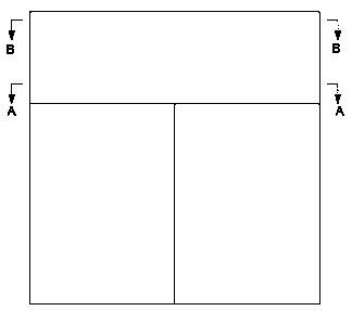
[0020] figure 1 It is an external schematic diagram of the overall structure of a wood drying device in the present invention;

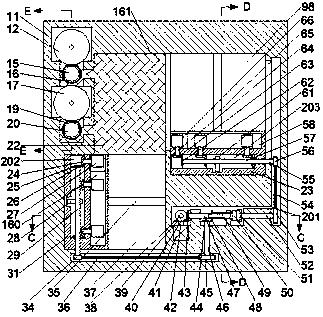
[0021] figure 2 Yes figure 1 Schematic diagram of the structure of A-A;

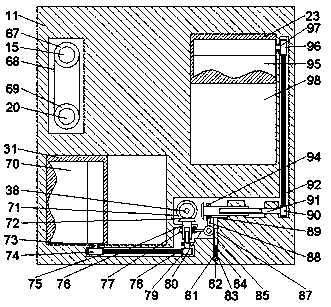
[0022] image 3 Yes figure 1 Schematic diagram of the structure of B-B;

[0023] Figure 4 Yes figure 2 Schematic diagram of the structure of C-C;

[0024] Figure 5 Yes figure 2 Schematic diagram of the structure of D-D;

[0025] Image 6 Yes figure 2 Schematic diagram of the structure of E-E;

[0026] Figure 7 Yes Image 6 Schematic diagrams of the structures of F–F.

[0027] like Figure 1-Figure 7As shown, a wood drying device of the present invention includes a fuselage 11 and a first cavity 201 is arranged in the fuselage 11, and a first rotating shaft 40 extending forward and backward is rotatably arranged in the first cavity 201. , the front end of the first rotating shaft 40 is power-connected with the motor 41 arranged in the front end wall of t...


PUM


Abstract

The invention discloses a wood drying device which adopts a machine body and a first cavity formed in the machine body. A first rotary shaft extending in a front-back way is rotatably arranged in thefirst cavity, the front-side tail end of the first rotary shaft is in power connection with a motor arranged in the front-side end wall of the first cavity, a first bevel gear is fixedly arranged at the tail end of the back side of the first rotary shaft, a second rotary shaft extending in a left-right way is rotatably arranged in the first cavity, and the left-side tail end of the second rotary shaft is fixedly provided with a second bevel gear meshed with the first bevel gear. The device is simple in structure, reliable in performance and convenient to install, maintain and repair. In addition, artificial intervention is not needed in the operating process of the device, automatic processing of the device is achieved, the wood kilning efficiency is improved, meanwhile wood separating distance control of wood kilning is accurate, the influence of different wood separating distances on woods in the drying process is avoided, and meanwhile the automation degree and practicality of the device are improved.

Description

technical field [0001] The invention relates to the field of wood processing, in particular to a wood drying device. Background technique [0002] With the development of society, the demand for wood products is increasing, so the requirements for wood processing are getting higher and higher. Drying the wood before wood processing can not only reduce the weight of the wood but also increase the strength of the wood. However, before the wood is dried, kiln stacking is required. At present, most of the kiln stacking is done by manpower, which greatly affects the processing efficiency and labor cost. Therefore, a new type of equipment is needed to solve this problem. Contents of the invention [0003] The object of the present invention is to provide a wood drying device for overcoming the above-mentioned defects in the prior art. [0004] The present invention is achieved through the following technical solutions: a wood drying device of the present invention includes a fu...

Claims


Application Information

Patent Timeline
Patent Type & Authority Applications(China)
IPC IPC(8): F26B25/00
CPCF26B25/003F26B2210/16
Inventor 任霄原
Owner SHAOXING XIHENG TECH CO LTD
Learn More