
Calibration device for mounting positions of vehicle-mounted millimeter-wave radars and calibration method thereof

A millimeter-wave radar and installation location technology, applied in radio wave measurement systems, instruments, etc., can solve the problems of multiple formulas, complex calculations, inapplicable calibration and installation, etc., to ensure detection performance, improve installation accuracy, and ensure driving safety Effect

Pending Publication Date: 2019-01-18
芜湖易来达雷达科技有限公司
View PDF12 Cites 23 Cited by
  • Summary
  • Abstract
  • Description
  • Claims
  • Application Information

AI Technical Summary

Problems solved by technology

The present invention utilizes the common detection area of ​​the front / rear radar and the side radar to display the position information of the same target through the front / rear radar and the side radar, and can complete the calibration of the front / rear radar and the side radar, but The radar calibration method in this patent needs to be calibrated with the cooperation of other installed radars and cannot calibrate the installation position and attitude of the radar used alone. At the same time, there are many formulas in this patent and the calculation is complicated, which is not suitable for quick and simple calibration and installation, so there are still limitations

Method used


Image

  • Calibration device for mounting positions of vehicle-mounted millimeter-wave radars and calibration method thereof
  • Calibration device for mounting positions of vehicle-mounted millimeter-wave radars and calibration method thereof
  • Calibration device for mounting positions of vehicle-mounted millimeter-wave radars and calibration method thereof

Examples


Embodiment Construction

[0027] In order to make the technical means, creative features, goals and effects achieved by the present invention easy to understand, the present invention will be further elaborated below.

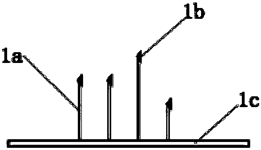
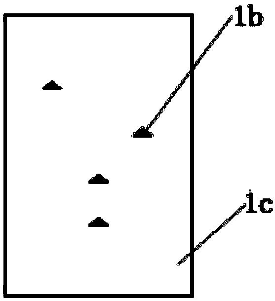
[0028] Such as Figure 1 to Figure 4 As shown, a calibration device for the installation position of a vehicle-mounted millimeter-wave radar includes a radar 2 arranged on the vehicle, and a calibration target group 1 set in front of the radar 2 for determining the installation position of the radar 2. The calibration target Group 1 includes a base 1c, and a set of support rods 1a arranged on the base 1c, and each set of support rods 1a is provided with a corner reflector 1b capable of reflecting millimeter waves.

[0029] The radar 2 is a vehicle-mounted millimeter-wave radar, and the radar 2 cooperates with communication equipment and a computer equipped with a calibration program.

[0030] During the calibration process, the calibration target group 1 is placed at a fixed position i...


PUM


Abstract

The invention relates to the field of mounting calibration of vehicle-mounted millimeter-wave radars, in particular to a calibration device for mounting positions of vehicle-mounted millimeter-wave radars and a calibration method thereof. The calibration device comprises a radar which is arranged on a vehicle and a calibration target group which is arranged in front of the radar and is used for determining a mounting position of the radar, wherein the calibration target group comprises a base and multiple groups of support rods which are arranged on the base; and a corner reflector capable ofreflecting millimeter waves is arranged on each group of support rods. The calibration method specifically comprises the following steps of: S1, positioning, S2, calibration, S3, information transmission, S4, comparison, S5, correction, and S6, calibration. The calibration device and the calibration method can be widely applied to the offline mounting calibration of vehicles equipped with vehicle-mounted millimeter-wave radars so as to improve the radar mounting precision, ensure the radar detection performance and ensure the vehicle running safety.

Description

technical field [0001] The invention relates to the field of installation and calibration of a vehicle-mounted millimeter-wave radar, in particular to a calibration device and a calibration method for the installation position of a vehicle-mounted millimeter-wave radar. Background technique [0002] With the development of science and technology, the emergence of vehicle-mounted intelligent active safety technology has further improved the driving safety of vehicles, and at the same time, it has put forward higher requirements for vehicle-mounted millimeter-wave radar, which is an important part of Advanced Driver Assistant System and ADAS. . The vehicle-mounted millimeter-wave radar detects and analyzes the surrounding road conditions while the vehicle is driving by sending and receiving millimeter-wave electromagnetic waves. As a sensor, the radar works in a spherical coordinate system with itself as the origin of the center of the sphere. Therefore, the deviation of the ...

Claims


Application Information

Patent Timeline
IPC IPC(8): G01S7/40
CPCG01S7/40
Inventor 李铮王征杨路路江子健叶祥罗畅安
Owner 芜湖易来达雷达科技有限公司
Learn More