Power conversion system, and overcurrent protection circuit and method for power switch transistor
A technology for overcurrent protection circuits and power switch tubes, which is applied in the direction of emergency protection circuit devices and electrical components, and can solve problems such as damage to power switch tubes, so as to avoid voltage overshoot, improve stability and safety, and slow down shutdown speed effect
- Summary
- Abstract
- Description
- Claims
- Application Information
AI Technical Summary
Problems solved by technology
Method used
Image

Examples
Embodiment 1
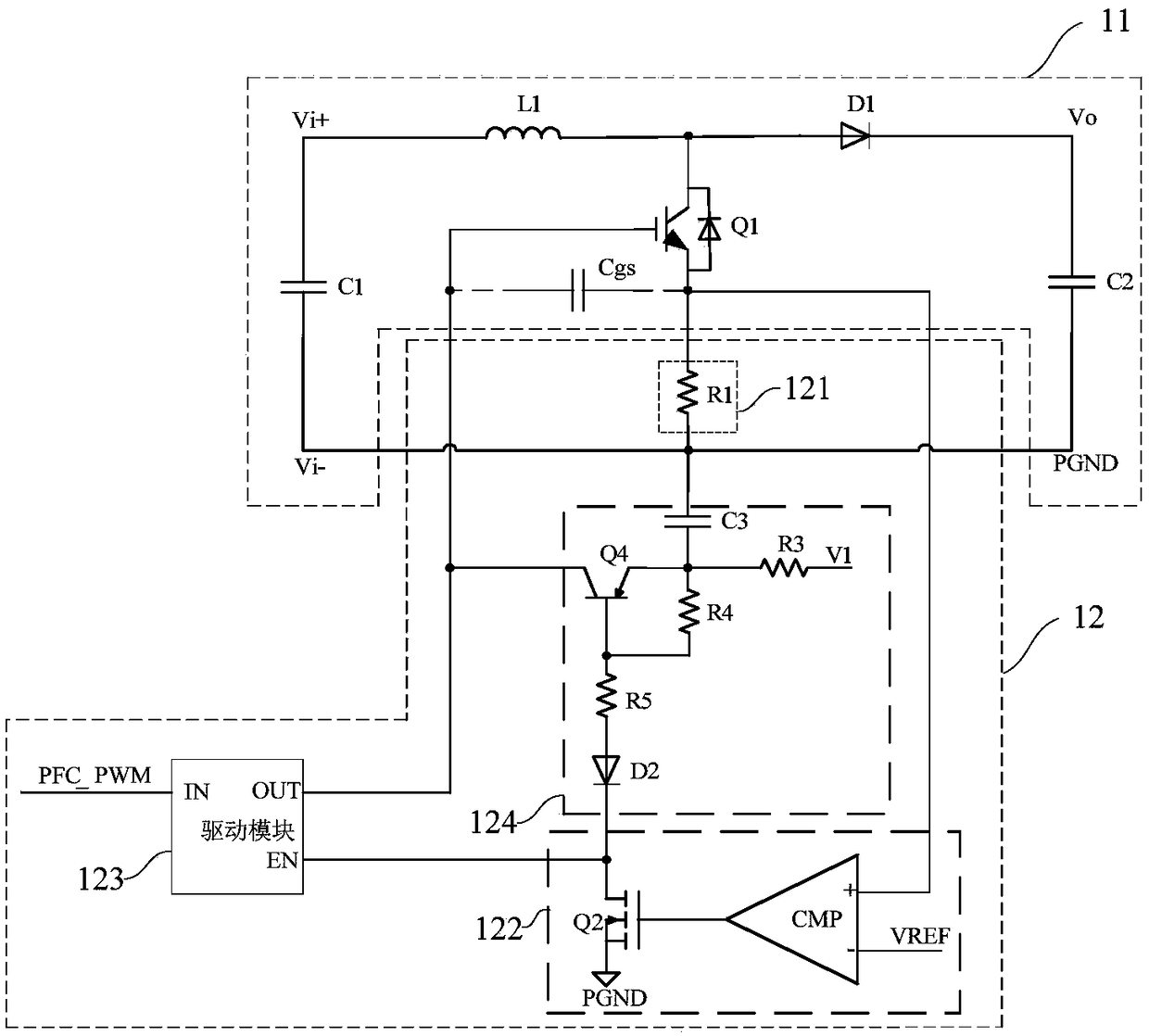
[0063] Such as figure 1 As shown, the present invention provides a power conversion system 1, and the power conversion system 1 includes:
[0064] The power conversion circuit 11 and the overcurrent protection circuit 12 of the power switch tube.
[0065] Such as figure 1 As shown, the input signal of the power conversion circuit 11 is an absolute value signal of alternating current, which is used to convert the absolute value signal of alternating current into a direct current bus voltage.
[0066] Specifically, the power conversion circuit 11 includes a PFC circuit, such as a boost circuit, a buck circuit or a buck-boost circuit, and different power conversion structures can be set according to needs, which are not limited to the examples in this embodiment. Such as figure 1 As shown, in this embodiment, the power conversion circuit 11 is a type of boost circuit, specifically including a filter capacitor C1, a reactor L1, a power switch tube Q1, a boost diode D1 and a smo...
Embodiment 2
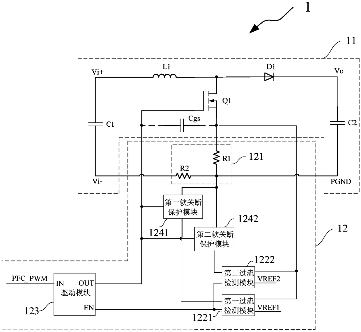
[0100] Such as figure 2 As shown, this embodiment provides a power conversion system. The difference from Embodiment 1 is that the overcurrent protection circuit 12 of the power switch tube also includes a second acquisition resistor R2, and the overcurrent detection module and Each of the soft-off protection modules includes two.
[0101] Specifically, one end of the second sampling resistor R2 is connected to the input negative electrode Vi- of the power conversion circuit 11, and the other end is connected to the reference ground PGND, and the second sampling resistor R2 detects the voltage of the power switch tube Q1. Input side current, the second sampling resistor R2 is connected to the control module (not shown in the figure) of the power switch tube Q1, the control module includes but not limited to a micro control unit (Microcontroller Unit; MCU), the control module Based on the current collected by the second sampling resistor R2, closed-loop control is performed t...
Embodiment 3
[0109] Such as Figure 4 As shown, this embodiment provides a power conversion system. The difference from Embodiment 2 is that the overcurrent protection circuit 12 of the power switch tube does not include the second acquisition resistor R2, and the overcurrent detection module and the Each of the soft-off protection modules includes three, and the output signal of each overcurrent detection module controls the input terminal, output terminal and enabling terminal of the driving module 123 respectively.
[0110]Specifically, the first output terminal of the first overcurrent detection module 1221 is connected to the input terminal of the driving module 123 , and the second output terminal is connected to the input terminal of the first soft-off protection module 1241 . The first output terminal of the second overcurrent detection module 1222 is connected to the enable terminal of the driving module 123 , and the second output terminal is connected to the input terminal of th...
PUM
 Abstract
Description
Claims
Application Information
 - R&D
- Intellectual Property
- Life Sciences
- Materials
- Tech Scout
- Unparalleled Data Quality
- Higher Quality Content
- 60% Fewer Hallucinations
Browse by: Latest US Patents, China's latest patents, Technical Efficacy Thesaurus, Application Domain, Technology Topic, Popular Technical Reports.
© 2025 PatSnap. All rights reserved.Legal|Privacy policy|Modern Slavery Act Transparency Statement|Sitemap|About US| Contact US: help@patsnap.com