
Method and apparatus for antenna calibration

An antenna calibration and antenna technology, applied in the field of communication systems, can solve the problems of the AC solution getting into trouble, occupying the GP or traffic symbol position, and increasing network delay, saving CPU processing cycles, reducing the negative impact of AC, The effect of prolonging sleep time

Active Publication Date: 2019-01-18
ERICSSON (CHINA) COMMUNICATION COMPANY LTD
View PDF4 Cites 5 Cited by
  • Summary
  • Abstract
  • Description
  • Claims
  • Application Information

AI Technical Summary

Problems solved by technology

This traditional AC utilizes fixed time intervals for acquisition and calculation, but this will occupy GP or traffic symbol positions and reduce transmission efficiency
[0012] In addition, because the 3GPP compatible AC interrupts the PDCCH, the delay of the network increases
The frequency at which the AC signal is sent cannot be slowed down due to strict antenna alignment requirements for beamforming and MIMO applications and rapid phase drift due to temperature changes
These conflicting requirements bog down AC solutions

Method used


Image

  • Method and apparatus for antenna calibration
  • Method and apparatus for antenna calibration
  • Method and apparatus for antenna calibration

Examples


Embodiment Construction

[0037]The following detailed description describes methods and apparatus for antenna calibration. In the following detailed description, reference is made to the accompanying drawings, which form a part hereof, and in which are shown by way of illustrations specific embodiments in which the disclosure may be practiced. These embodiments are described in sufficient detail to enable those skilled in the art to practice the disclosure, and it is to be understood that other embodiments may be utilized and that structural, logical and electrical changes. Therefore, the following detailed description should not be regarded as limiting, but illustrative. The scope of the present disclosure is defined by the appended claims and their equivalents.

[0038] The terminology used herein is for the purpose of describing particular embodiments only and is not intended to be limiting of the present disclosure. As used herein, the singular forms "a", "an", and "the" are intended to include...


PUM


Abstract

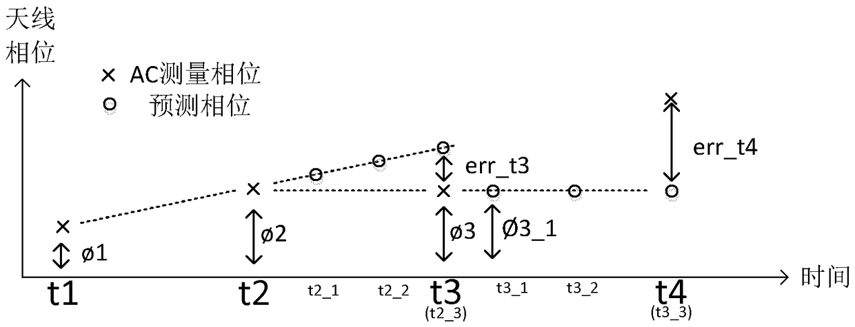
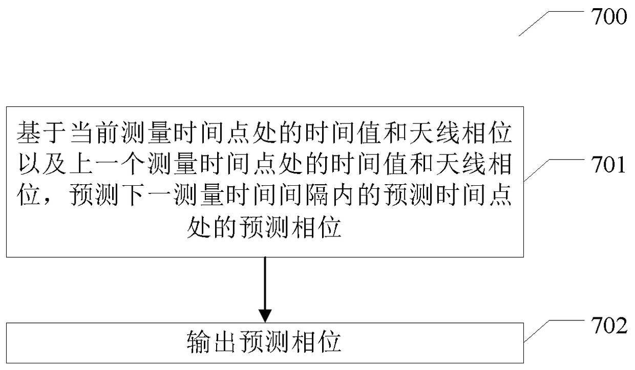
The present disclosure relates to a method for antenna calibration, includes predicting a predicted phase difference at a predetermined number of predicted time points within a next measurement time interval based on a time value at a previous measurement time point, a time value at a current measurement time point, an antenna phase difference measured at the previous measurement time point, and an antenna phase difference measured at the current measurement time point; and outputting a predicted phase difference at each predicted point in time. The present disclosure also relates to an apparatus for antenna calibration. With the prediction process of the present disclosure, the AC update interval can be significantly expanded, thereby reducing the negative impact of AC.

Description

technical field [0001] The present disclosure relates generally to communication systems, and more particularly to a method and apparatus for antenna calibration. Background technique [0002] This section will introduce various aspects that facilitate a better understanding of the present disclosure. Accordingly, the statements in this section should be read in this light and should not be construed as an acknowledgment of what is or is not prior art. [0003] An antenna array is a collection of antennas that have their own independent transmit / receive circuits (or branches) that work together to transmit and receive radio signals. Antenna arrays benefit communication systems in many ways. First, antenna arrays can achieve narrower beams of radio waves with higher transmit and receive gain. It can increase the coverage area without increasing the transmit and receive power. It is especially beneficial for mobile terminals with limited battery power supply. Second, ante...

Claims


Application Information

Patent Timeline
Patent Type & Authority Applications(China)
IPC IPC(8): H04B17/12
Inventor 杨劲松余晓东
Owner ERICSSON (CHINA) COMMUNICATION COMPANY LTD
Learn More