a vena cava filter

A vena cava and filter technology, applied in the field of medical devices, can solve the problem of no recognized filter, etc., and achieve the effects of reducing blood vessel tearing, improving fishing efficiency, and prolonging service life.

Active Publication Date: 2020-12-18
BEIJING TARGET TECH
View PDF10 Cites 0 Cited by
  • Summary
  • Abstract
  • Description
  • Claims
  • Application Information

AI Technical Summary

Problems solved by technology

[0004] At present, a filter with excellent performance on the market often means that it performs well in one or several aspects, that is to say, there is an ideal filter standard, but there is no recognized particularly excellent filter.

Method used


Image

  • a vena cava filter
  • a vena cava filter
  • a vena cava filter

Examples


Embodiment 1

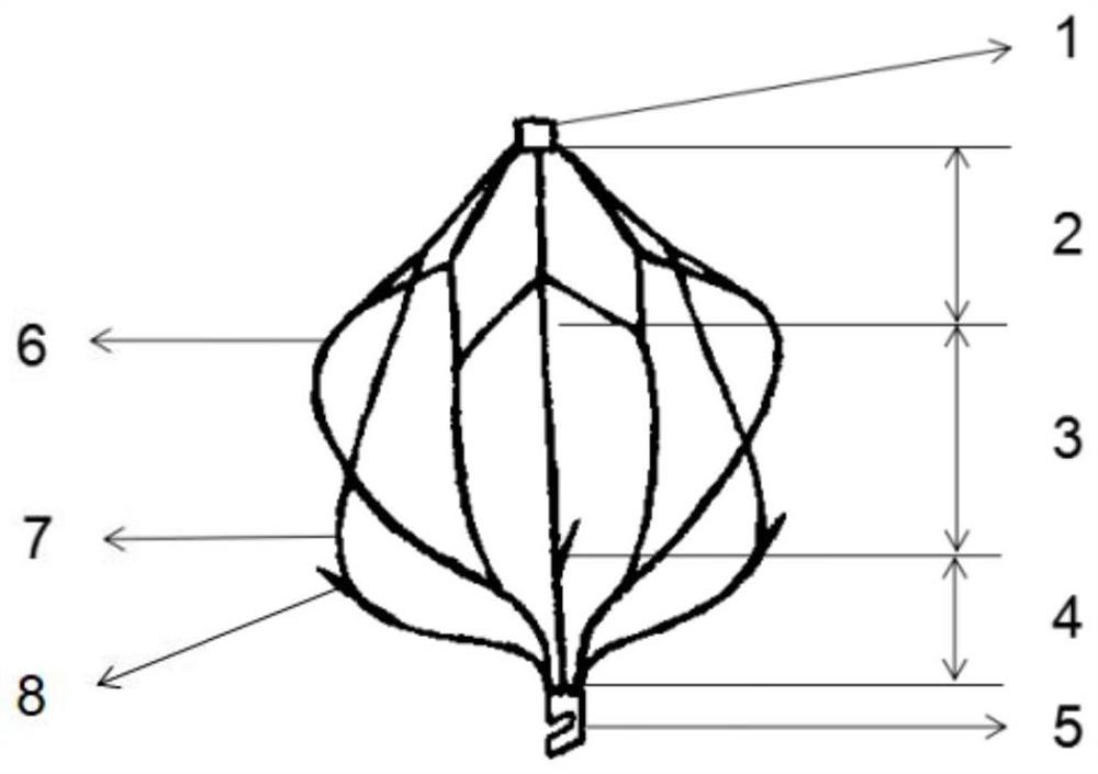
[0030] figure 1 with figure 2 The structural diagram of the vena cava filter provided in this embodiment is composed of a head end 1, an upper filter 2, a support section 3, a lower filter 4, and a recovery part 5 connected in sequence. The head end 1, the upper filter screen 2, the support section 3, the lower filter screen 4, and the recovery part 5 are all woven or cut from nickel-titanium and other shape memory alloy materials.

[0031] The head end 1 is a nickel-titanium tube, and the upper filter screen 2 is folded to facilitate recovery into the sheath; the head end 1 contains a nut for connecting with the delivery rod.

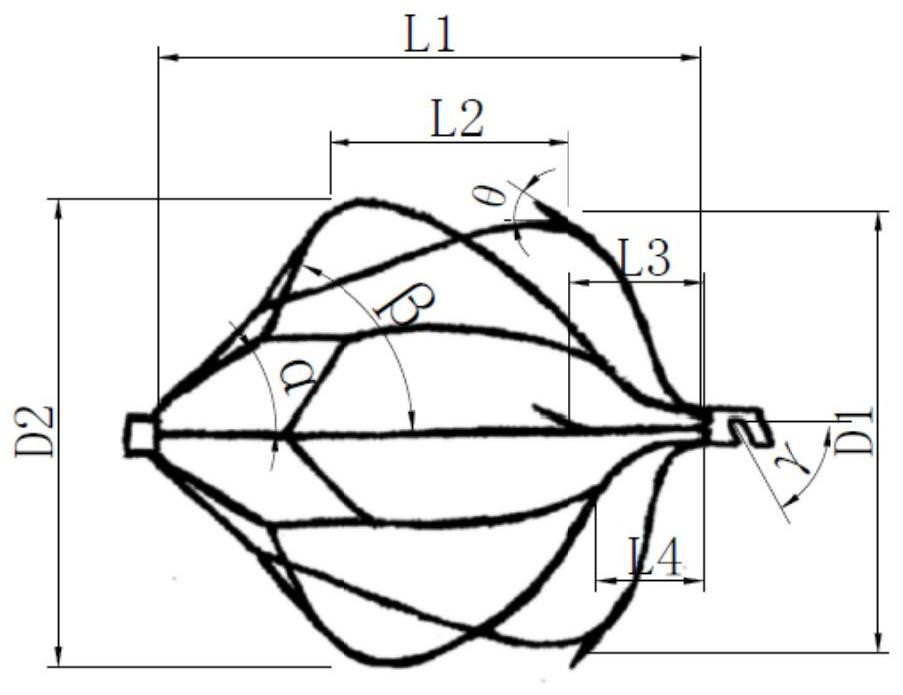
[0032] The upper filter net 2 is a petal shape formed by splicing a plurality of rhombic grids in a ring shape, and the rings are evenly distributed (central symmetry). From the upper end to the lower end, there are first-level grids and second-level grids. The vertex angles of each cell of the first-level grid and the second-level grid are α and β ...

Embodiment 2

[0046] The difference between this embodiment and Embodiment 1 lies in the design of the upper filter screen 2 .

[0047] In embodiment 1, such as figure 1 , the upper filter screen 2 is designed to contain a primary grid and a secondary grid, the rhombus tip of the upper filter screen 2 is connected at one end of the connecting rod 6, and the diamond-shaped concave end of the upper filter screen 2 is connected at one end of the support rod 7.

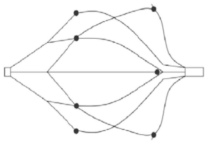
[0048] In this example, if Figure 4 The design of the upper filter screen 2 contains a primary grid, a secondary grid and a tertiary grid. One end of the connecting rod 6 is connected to the rhombus tip of the secondary grid of the upper filter screen 2, and one end of the support rod 7 is connected to the third end of the upper filter screen 2. level grid tip. In particular, the angle of the third-level grid is smaller than that of the second-level grid, which is the design of the transition part between the support rod 7 and the u...

Embodiment 3

[0050] The difference between this embodiment and Embodiment 1 lies in the design of the connecting rod 6 .

[0051] In embodiment 1, such as figure 1 with figure 2 , the connecting rod 6 is merged into a single strand at the distance L4 from the recovery part 7, and the merged position is designed to be located at the lower filter screen 4. At this time, there are 6 evenly distributed wires near the axis of the filter to filter and catch thrombus, and the position away from the axis of the filter is 3 evenly distributed wires are used to filter and catch thrombus.

[0052] In this example, if Figure 5 , it is designed that the merging position is located in the area of ​​the support section 3, at this time, the lower filter screen 4 contains 6 evenly distributed wires to filter and catch thrombus.


PUM


Abstract

The invention provides a vena cava filter. The vena cava filter is constituted by a head end, an upper end filter net, a supporting section, a lower end filter net and a recovery part which are connected sequentially. The upper end filter net is formed by a plurality of rhombic grids which are annularly spliced. The top of the upper end filter net is closed by the head end. The supporting sectionis constituted by the upper portions of connecting rods and the upper portions of supporting rods. The lower end filter net is constituted by the lower portions of the connecting rods and the lower portions of the supporting rods. The connecting rods and the supporting rods are distributed in a spatially staggered mode. The radians of the connecting rods are decreased from top to bottom, and the radians of the supporting rods are increased from top to bottom. The positions, with the maximum outer diameters, of the connecting rods and the supporting rods are located at the two ends of the supporting section correspondingly. The positions, with the maximum outer diameters, of the supporting rods are provided with barbs. The bottom of the lower end filter net is closed by the recovery part. According to the vena cava filter, the point contact mode is constituted by the supporting rods and the connecting rods with the simple and convenient radians jointly, contact with blood vessels can bereduced, self-centrality and stability of the vena cava filter can also be ensured, the thrombus catching efficiency is improved, and the recovery difficulty is reduced.

Description

technical field [0001] The invention relates to a vena cava filter, which is used for catching thrombus in the vena cava, and belongs to the technical field of medical instruments. Background technique [0002] The inferior vena cava filter (IVCF) is a device designed to prevent pulmonary embolism caused by emboli in the inferior vena cava system. After more than 40 years of continuous improvement, the variety of filters has increased and the filtering effect has improved, significantly reducing the incidence of pulmonary embolism. [0003] An ideal vena cava filter should have the following characteristics: 1) A relatively wide time window can prevent pulmonary embolism while avoiding adverse reactions caused by long-term implantation, and the recovery time should not be limited by the recommended recovery time of the device itself; 2) Good thrombus capture performance; 3) Good fixation, including not easy to shift, tilt and maintain symmetrical placement in blood vessels;...

Claims


Application Information

Patent Timeline
Patent Type & Authority Patents(China)
IPC IPC(8): A61F2/01
CPCA61F2/01A61F2002/016A61F2/011
Inventor 张红梅杨永森李博曾凡艳耿聪颖曹维拯陈娟
Owner BEIJING TARGET TECH
Why Eureka
Try Eureka