
Tail gas treatment method and device for salt extraction facility, sulfur warehouse, and sulfur-melting kettle of coking plant

A technology for melting sulfur kettles and coking plants, applied in the field of waste gas treatment in coking plants, which can solve problems such as pollution emissions, affecting human health, polluting air, etc., and achieves a reasonable effect of device composition

Pending Publication Date: 2019-01-22
山东环达环保科技有限公司
View PDF6 Cites 2 Cited by
  • Summary
  • Abstract
  • Description
  • Claims
  • Application Information

AI Technical Summary

Problems solved by technology

[0002] The coking plant will produce harmful tail gas in the production of salt extraction, which needs to be treated; the sulfur warehouse will emit pungent smell and harmful gas when stacking and transferring materials, which needs to be treated; the sulfur melting kettle will emit pungent odor and harmful gas during production, It needs to be treated, and if it is not treated, the emission will pollute the air and affect personal health. Environmental protection requirements need to be treated to meet the standards. The current manufacturers generally collect the exhaust gas and then discharge it. There is a problem with this treatment method. It is impossible for any equipment to be completely correct. Exhaust gas treatment; moreover, the so-called up-to-standard discharge can only mean that the discharge of pollutants below a certain standard will actually produce polluting discharge

Method used


Image

  • Tail gas treatment method and device for salt extraction facility, sulfur warehouse, and sulfur-melting kettle of coking plant

Examples


Embodiment Construction

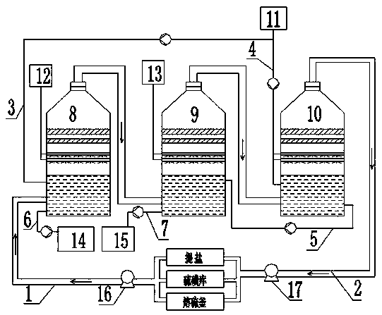
[0019] As shown in the figure, there is a coking plant salt extraction facility, sulfur storehouse, and sulfur melting tank tail gas treatment device. The exhaust gas emitted by the sulfur kettle is collected by the collection equipment and then introduced into the air inlet at the lower part of the closed pickling spray tower through the pipeline and fan for pickling, and the gas after pickling passes through the gas outlet at the upper part of the pickling spray tower and The pipeline is introduced into the air inlet at the lower part of the closed alkali washing spray tower for alkali washing, and the gas after alkali washing is then introduced into the air inlet at the lower part of the closed water washing spray tower through the outlet at the upper part of the alkali washing spray tower and the pipeline , carry out water washing, and the gas after water washing is sent to the collection point of salt extraction, sulfur storage, and sulfur melting kettle by one fan or mult...


PUM


Abstract

The invention discloses a tail gas treatment method for a salt extraction facility, a sulfur warehouse, and a sulfur-melting kettle of a coking plant, which comprises the following steps: collecting the waste gas generated in salt extraction production, the waste gas emitted from the materials of the sulfur warehouse, and the waste gas emitted from the sulfur-melting kettle in production of the coking plant by a collection device, introducing into the lower part of a closed pickling spray tower via a pipeline and a fan, pickling, introducing the pickled gas into the lower part of the closed alkali washing spray tower, alkali washing, introducing the gas subjected to alkali washing to the gas inlet of the lower part of a closed water washing spraying tower by the outlet of the upper part ofan alkali washing spray tower and pipelines, water washing, transporting back the gas subjected to water washing to the collection points of salt extraction, the sulfur warehouse, and the sulfur-melting kettle by the fan, and finally circulating the waste gas for returning and utilization, to achieve zero discharge of tail gas treatment. The entire process and device structure are reasonable, inthe case of energy saving, coking plant resources are utilized maximally, and tail gas generated by the salt extraction facility, the devices, the sulfur warehouses, and the sulfur-melting kettles iscollected and treated centrally, realizing circulation treatment and energy saving and consumption reduction, without discharging.

Description

technical field [0001] The invention relates to a waste gas treatment technology of a coking plant, in particular to a method and a device for treating tail gas of a salt extraction facility, a sulfur storehouse, and a sulfur melting kettle. Background technique [0002] The coking plant will produce harmful tail gas in the production of salt extraction, which needs to be treated; the sulfur warehouse will emit pungent smell and harmful gas when stacking and transferring materials, which needs to be treated; the sulfur melting kettle will emit pungent odor and harmful gas during production, It needs to be treated, and if it is not treated, the emission will pollute the air and affect personal health. Environmental protection requirements need to be treated to meet the standards. The current manufacturers generally collect the exhaust gas and then discharge it. There is a problem with this treatment method. It is impossible for any equipment to be completely correct. Exhaust ...

Claims


Application Information

Patent Timeline
Patent Type & Authority Applications(China)
IPC IPC(8): B01D53/78
CPCB01D53/78
Inventor 彭圭
Owner 山东环达环保科技有限公司
Learn More