Heat radiation 3D printing machine with discharge hatch roll shaft provided with protection structure

A 3D printer and protection structure technology, applied in the direction of additive processing, etc., can solve the problems of reducing the working efficiency of the device, increasing the degree of wear of the roller shaft, and high temperature of the device, preventing collapse, smooth discharge work, and enhanced connectivity. Effect

Inactive Publication Date: 2019-01-22
DONGGUAN KAILEDI NUMERICAL CONTROL SCI & TECH CO LTD
View PDF0 Cites 0 Cited by
  • Summary
  • Abstract
  • Description
  • Claims
  • Application Information

AI Technical Summary

Problems solved by technology

[0004] The purpose of the present invention is to provide a heat-dissipating 3D printer with a protective structure for the roller shaft at the discharge port, so as to solve the problem that the roller shaft at the discharge port does not have protection during use of the existing 3D printer proposed in the background technology. structure, resulting in increased roller wear, affecting the normal performance of the device, and when the device is working, the heat dissipation performance is not good, making the temperature of the device too high and reducing the working efficiency of the device

Method used


Image

  • Heat radiation 3D printing machine with discharge hatch roll shaft provided with protection structure
  • Heat radiation 3D printing machine with discharge hatch roll shaft provided with protection structure
  • Heat radiation 3D printing machine with discharge hatch roll shaft provided with protection structure

Examples


Embodiment Construction

[0026] The following will clearly and completely describe the technical solutions in the embodiments of the present invention with reference to the accompanying drawings in the embodiments of the present invention. Obviously, the described embodiments are only some, not all, embodiments of the present invention. Based on the embodiments of the present invention, all other embodiments obtained by persons of ordinary skill in the art without making creative efforts belong to the protection scope of the present invention.

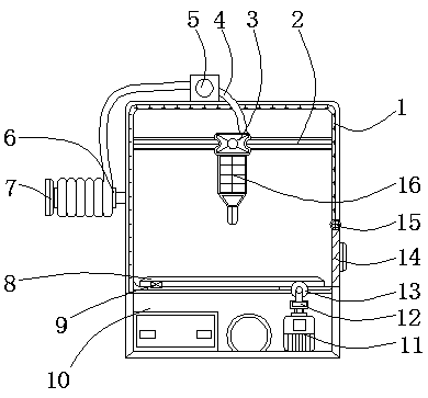
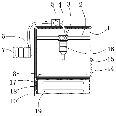
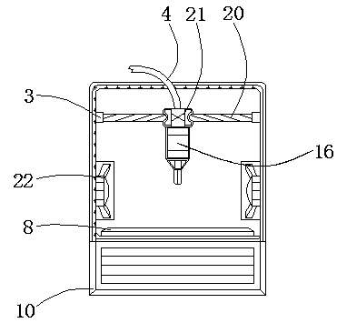
[0027] see Figure 1-5 , the present invention provides a technical solution: a heat-dissipating 3D printer with a protective structure for the roller shaft of the discharge port, including a main body 1, a fixed rod 2, a first movable box 3, a material strip 4, a guide block 5, a roller 6, Support rod 7, printing tray 8, slider 9, base 10, servo motor 11, coupling shaft 12, roller shaft 13, movable plate 14, movable shaft 15, printing cylinder 16, door shaft ...


PUM


Abstract

The invention relates to a heat radiation 3D printing machine with a discharge hatch roll shaft provided with a protection structure. The heat radiation 3D printing machine comprises a main body, a roll shaft, and a bar-shaped ventilating opening; a fixed rod is arranged at the internal wall of the main body; the external side of the fixed rod is movably provided with a first movable box; the internal side of the first movable box close to the central axis of the main body is connected with a movable rod; the external side of the movable rod is movably provided with a second movable box; the top of the second movable box is provided with a material bar; and the external side of the material bar is provided with a direction guide block. The beneficial effects are that: a projection, a groove, the main body, and a heat radiation fan are adopted, and the external side of the projection is designed to match the internal wall of the groove, so that in relative moving operation of the roll shaft and a printing tray, under the mutual engaging effect of the projection on the external wall of the roll shaft and the groove on the internal side of the bottom of the printing tray, more smoothdischarging operation can be completed by the printing tray, and under the effect of the externally sealed printing tray, the roll shaft is protected in discharging.

Description

technical field [0001] The invention relates to the technical field of 3D printers, in particular to a heat-dissipating 3D printer with a protective structure for a roller shaft at a discharge port. Background technique [0002] With the development of science and technology and the progress of the social era, 3D printing technology is becoming more and more mature, and 3D printers can not only "print" a complete building, but can even print any required items for astronauts in spaceships. Shape, but 3D printing is the model of the object, not the function of the object. [0003] During the use of existing 3D printers, the roller shaft at the discharge port does not have a protective structure, resulting in increased wear of the roller shaft, affecting the normal working performance of the device, and when the device is working, the heat dissipation performance is poor, making the The temperature of the device is too high, reducing the working efficiency of the device. Co...

Claims


Application Information

Patent Timeline
IPC IPC(8): B29C64/20B33Y30/00
CPCB29C64/20B33Y30/00
Inventor 郭良山胡亚
Owner DONGGUAN KAILEDI NUMERICAL CONTROL SCI & TECH CO LTD
Why Eureka
Try Eureka