Backward sweep angle and upper/lower reflex angle directly controllable osculating cone waverider body design method

A design method and waverider technology, applied in the field of aerodynamic shape design of hypersonic aircraft, can solve problems such as inability to directly control

Active Publication Date: 2019-01-22
NAT UNIV OF DEFENSE TECH
View PDF6 Cites 12 Cited by
  • Summary
  • Abstract
  • Description
  • Claims
  • Application Information

AI Technical Summary

Problems solved by technology

[0008] Aiming at the defect that the two geometric shape parameters of leading edge line sweep angle and dihedral are coupled with each other and cannot be directly controlled in the general kiss-cut cone waverider design method, the present invention proposes A design method for kiss-cut cone waveriders with direct controllable sweep angle and dihedral angle

Method used


Image

  • Backward sweep angle and upper/lower reflex angle directly controllable osculating cone waverider body design method
  • Backward sweep angle and upper/lower reflex angle directly controllable osculating cone waverider body design method
  • Backward sweep angle and upper/lower reflex angle directly controllable osculating cone waverider body design method

Examples


Embodiment Construction

[0117] The following will clearly and completely describe the technical solutions in the embodiments of the present invention in combination with the accompanying drawings in the embodiments of the present invention, and give further detailed descriptions, but the scope of protection of the present invention will not be limited accordingly.

[0118] The following will clearly and completely describe the technical solutions in the embodiments of the present invention in combination with the accompanying drawings in the embodiments of the present invention, and give further detailed descriptions, but the scope of protection of the present invention will not be limited accordingly.

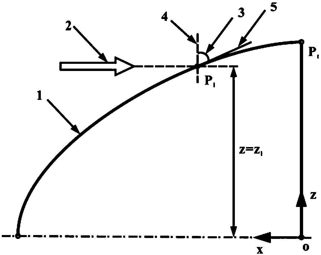
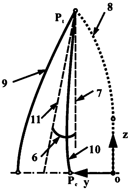
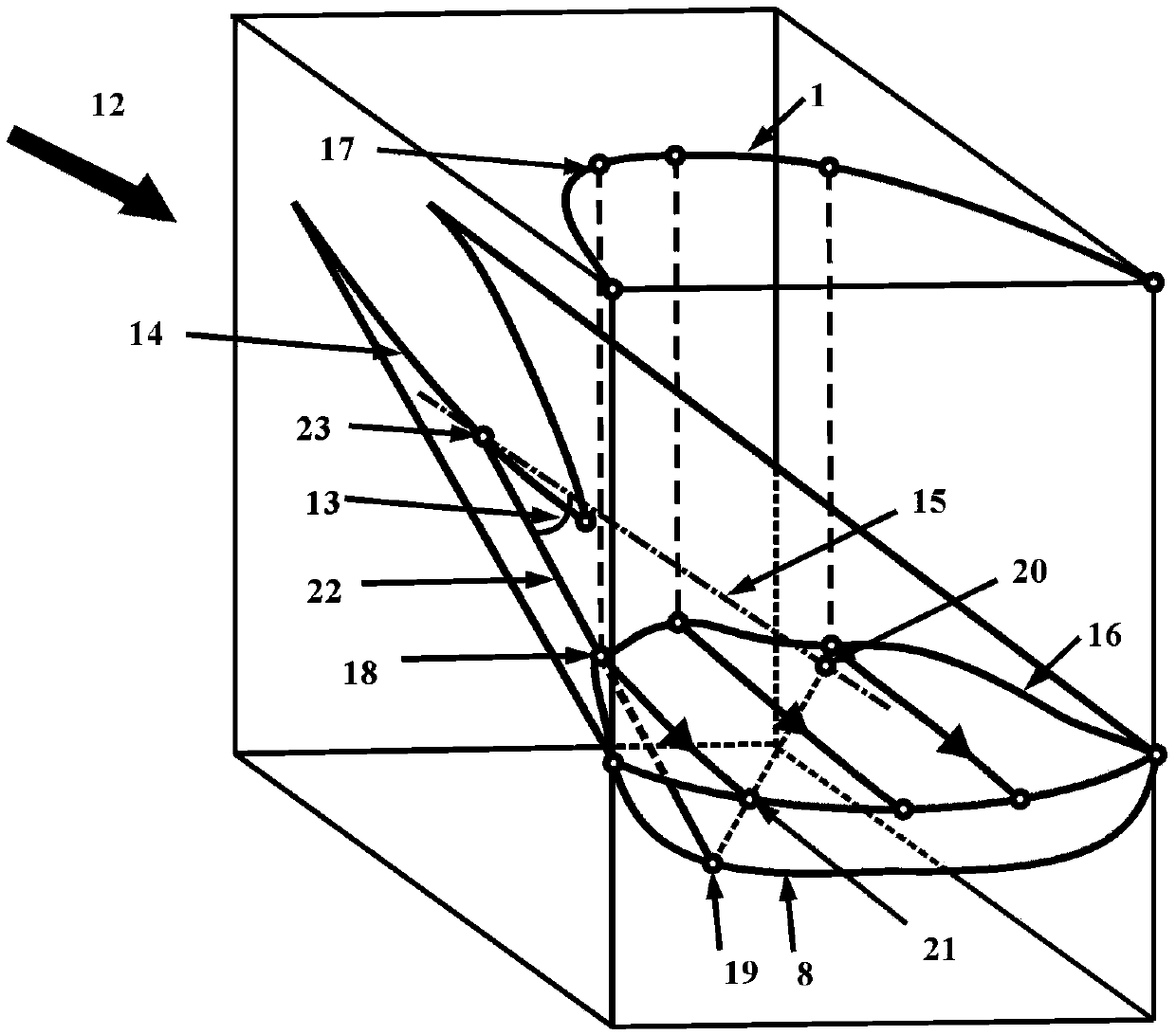
[0119] A method for designing a kiss-cut cone waverider with directly controllable sweep angle and dihedral angle, including the following steps:

[0120] S1: The reference flow field parameters are given, where the reference flow field parameters include incoming flow Mach number Ma and shock angle β...


PUM


Abstract

The invention provides a backward sweep angle and upper / lower reflex angle directly controllable osculating cone waverider body design method which includes such steps as setting reference flow fieldparameters, setting the backward sweep angle of the horizontal projection line of the leading edge of the wavefront, along the z-direction of the body coordinate system, that is, setting a backward sweep angle equation, and solving horizontal projection profile of leading edge of multiply wave body; then, designing and solving the cross-sectional profile of the bottom of the shock wave, and solving the leading edge points on the leading edge line of the wave-multiplier; then, generating the streamline which constitutes the lower surface of the wave-multiplier by the forward streamline tracingmethod from the leading edge points, and finally generating the wave-multiplier by geometric lofting. Based on the design method, the invention realizes the ultimate goal of controllable sweep angle and upper anti-angle of the leading edge line of the snapping cone multiplier.

Description

technical field [0001] The invention belongs to the technical field of aerodynamic shape design of hypersonic aircraft, and in particular relates to a design method of a kiss-cut cone waverider whose sweep angle and up / down anhedral angle of the waverider are directly controllable. Background technique [0002] A hypersonic vehicle is an aircraft with a speed exceeding Mach 5, including air-breathing hypersonic vehicles, rocket-powered hypersonic vehicles, and unpowered gliding vehicles. Specific applications include hypersonic cruise missiles, hypersonic manned / unmanned aircraft, and air Airplanes and more. [0003] In order to pursue good cruise and strike performance, a hypersonic vehicle must have a high lift-to-drag ratio and a large available space to increase the proportion of payload in the total volume. [0004] The aerodynamic shape of hypersonic vehicles mainly includes three types: axisymmetric configuration, lifting body configuration and waverider configuratio...

Claims


Application Information

Patent Timeline
IPC IPC(8): B64F5/00B64C30/00
CPCB64C30/00B64F5/00
Inventor 陈韶华柳军丁峰刘珍王晓燕罗仕超蒋浩张文浩
Owner NAT UNIV OF DEFENSE TECH
Why Eureka
Try Eureka