Banded transportation junction formed by paralleling parallel elevated road stations and elevated railway stations

A transportation hub and elevated road technology, which is applied to elevated railways, elevated railway systems without suspended vehicles, stations, etc., can solve the inconvenience of large integrated transportation hubs, the inconvenience of commercial development around large integrated transportation hubs, and the inconvenience of separation of transportation and commerce. and other problems to achieve the effect of reducing urban traffic

Active Publication Date: 2010-10-27
田耕
View PDF11 Cites 14 Cited by
  • Summary
  • Abstract
  • Description
  • Claims
  • Application Information

AI Technical Summary

Problems solved by technology

[0028] [1] The technical problem to be solved by the belt-shaped traffic hub composed of parallel elevated road stations and elevated railway passenger stations proposed by the present invention is: at present, the stops of various traffic modes in large-scale comprehensive traffic hubs with passenger dedicated lines and high-speed rail as the core Excessive aggregation, excessive concentration of transfer functions, too large scale, and long walking distance for passengers; large comprehensive transportation hubs are not easy to approach by walking, and the surrounding areas of large comprehensive transportation hubs are not convenient for commercial development. Inconvenient, increasing the total amount of urban traffic

Method used


Image

  • Banded transportation junction formed by paralleling parallel elevated road stations and elevated railway stations
  • Banded transportation junction formed by paralleling parallel elevated road stations and elevated railway stations
  • Banded transportation junction formed by paralleling parallel elevated road stations and elevated railway stations

Examples


Embodiment Construction

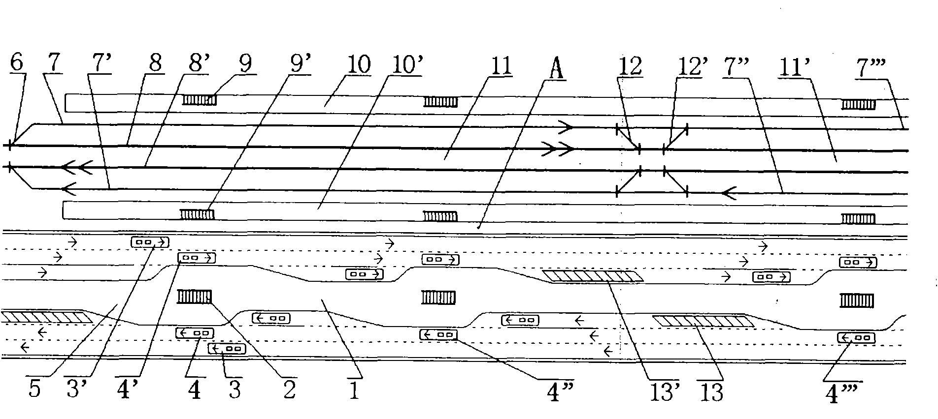
[0058] figure 1 It is a schematic plan view of the principle plane of a belt-shaped transportation hub composed of parallel elevated road stations and elevated railway passenger stations. figure 1 It is marked in: the island platform 1 of the parallel viaduct station, the stairs 2, the expressway and the vehicle 3, 3', the parking station and the bus stop 4, 4', 4", 4'", the parallel viaduct station 5, Railway turnout 6, railway passenger station arrival and departure line and train 7, 7', 7", 7'", railway main line and train 8, 8', stairs 9, 9', railway passenger station side platform 10, 10', elevated Railway passenger station 11, 11', railway turnout 12, 12', emergency parking area 13, 13' of parallel elevated road; figure 1 The large double arrows in indicate the trains on the main line and their direction of travel, figure 1 The large single arrow in indicates the train on the departure line and its head direction, figure 1 The small arrow in indicates the driving...


PUM


Abstract

The invention relates to a banded transportation junction formed by paralleling parallel elevated road stations and elevated railway stations, belonging to the technical field of railway station construction and aiming at solving the problem of inconvenience brought about for people by the conditions that the stations of various transport means of a large-scale integrated transportation junction are excessively concentrated, a scale is excessively huge, and transport is separated from commerce. The parallel elevated road stations are arranged parallel to one or more than one elevated railway station at short distances to form the banded transport hub; stop stations of island platforms of the parallel elevated road stations correspond to entrances/exits of the elevated railway stations, and passengers can take buses which are convenient for positive-direction and reverse-direction transfer on parallel elevated roads to reach and leave the entrances/exits of elevated railway stations on which the passengers need to take; and when the parallel elevated road stations are parallel to the elevated railway stations in an overlapping way, the parallel elevated road stations are positioned below the elevated railway stations.

Description

(1) Technical field: [0001] The invention relates to the construction technology of a railway passenger station, in particular to a belt-shaped traffic hub composed of a parallel elevated railway station and an elevated railway passenger station. (two) background technology: [0002] Passenger dedicated lines and high-speed trains have high train speeds, large distances between stations, and a large service radius at each station. Passengers come and go as they go, and railway passenger transport is the development direction. The transfer between urban traffic and railway passenger stations is one of the key links for passenger dedicated lines and high-speed rail to fully function. [0003] At present, the main problems of large-scale comprehensive transportation hubs with passenger dedicated lines and high-speed rail as the core are: excessive concentration of stops of various transportation methods, excessive concentration of transfer functions, excessive scale, and long ...

Claims


Application Information

Patent Timeline
Patent Type & Authority Applications(China)
IPC IPC(8): B61B1/00B61B5/00
Inventor 田耕
Owner 田耕
Why Eureka
Try Eureka