Complete equipment for garbage transfer

A complete set of equipment and garbage transfer technology, applied in the direction of garbage cans, garbage delivery, garbage collection, etc., can solve the problems of sewage dripping, falling out, poor working environment, etc., and achieve the effect of reducing the burden

Inactive Publication Date: 2019-01-22
杭州俊盛机电有限公司
View PDF9 Cites 4 Cited by
  • Summary
  • Abstract
  • Description
  • Claims
  • Application Information

AI Technical Summary

Problems solved by technology

However, in the process of transferring the garbage from the hopper to the garbage compression device, the garbage contained in the hopper will often fall out of the hopper, r

Method used


Image

  • Complete equipment for garbage transfer
  • Complete equipment for garbage transfer
  • Complete equipment for garbage transfer

Examples


Example Embodiment

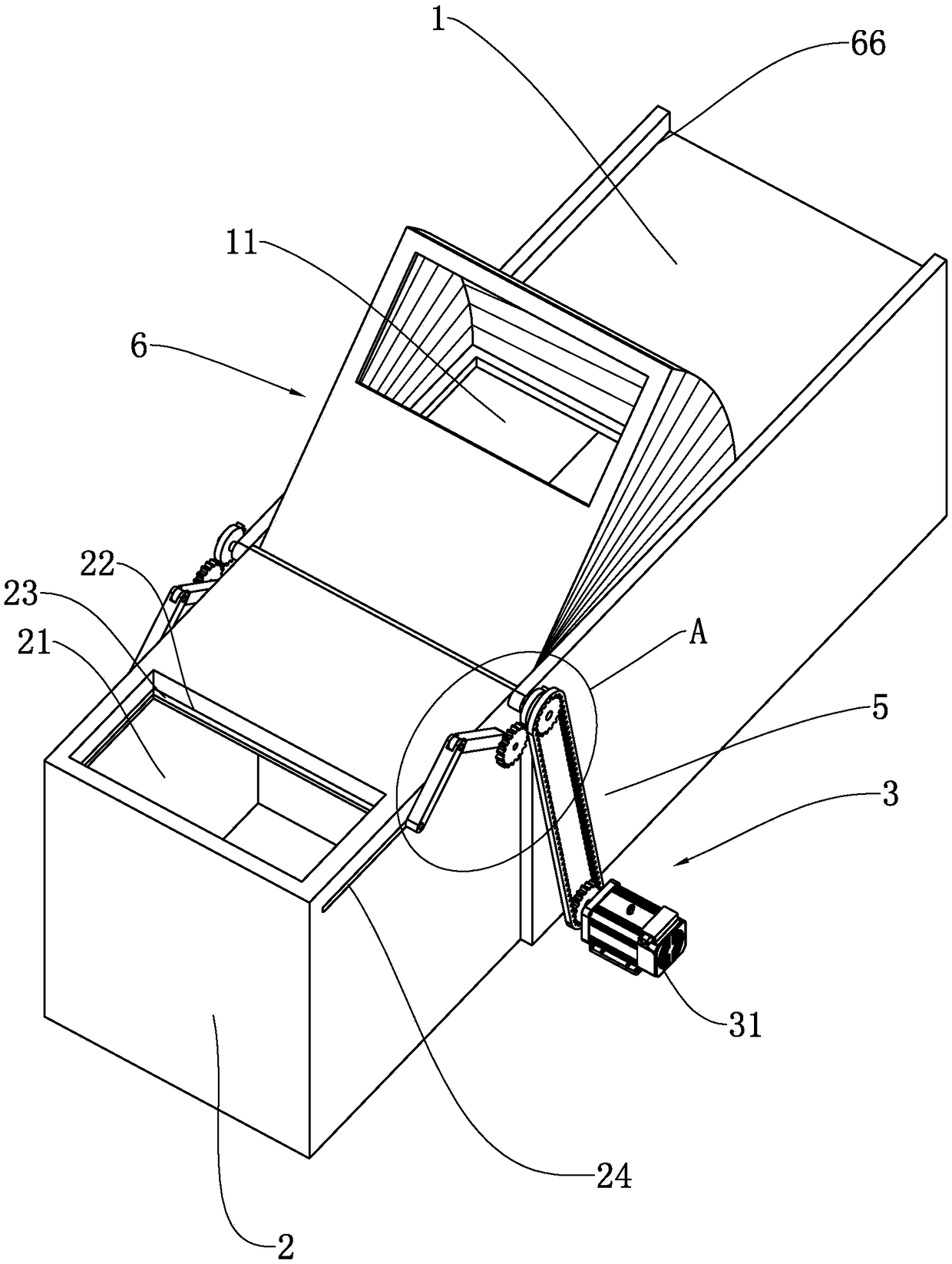
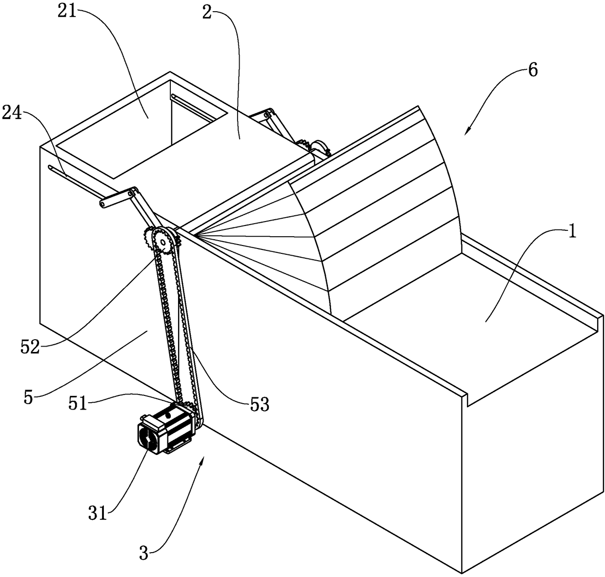
[0036] Embodiment 1: A complete set of garbage transfer equipment, such as figure 1 , figure 2 As shown, it includes a garbage compression device 1 provided with a first feeding port 11, a storage box 2 rotatably connected to the opening end of the garbage compression device 1, a drive device 3 located between the storage box 2 and the garbage compression device 1, Wherein, the top of the storage box 2 is provided with a second feed port 21 coordinating with the first feed port 11, and the side wall of the second feed port 21 is provided with a storage tank 22, which is slidably connected with a closed second feed port 22 in the storage tank 22. Closing plate 23 for port 21. When the garbage compression device 1 handles the garbage, the garbage to be processed is put into the storage box 2, so that after the garbage compression device 1 compresses the garbage, new garbage can be quickly filled into the garbage compression device 1; During the process of filling the bin 2 in...

Example Embodiment

[0044] Embodiment 2: A complete set of garbage transfer equipment such as Figure 7 As shown, the difference from Embodiment 1 is that when the storage box 2 is close to the garbage compression device 1, the closing plate 23 will be opened, and the garbage may still fall out of the storage box 2 to the ground during this process, so in this The first feed port 11 is provided with a shielding mechanism 6 that cooperates with the material storage box 2 and wraps the second feed port 21 .

[0045] like Figure 7 As shown, the blocking mechanism 6 includes a blocking plate 61 that is rotatably connected to the garbage compacting device 1, and a folding frame 62 that is connected between the garbage compacting device 1 and the blocking plate 61, wherein the blocking plate 61 is provided to cooperate with the second feeding port 21. The pouring opening 63, the folding frame 62 includes folding straight plates 64 connected to both sides of the shielding plate 61, and folding arc pla...


PUM


Abstract

The invention relates to the field of garbage treatment, in particular to complete equipment for garbage transfer. The equipment aims at solving the problem that when poured into a garbage compressiondevice from a storage box, garbage is scattered to the ground. The equipment is characterized by comprising a garbage compression device provided with a first feeding port, a storage box and a driving device, a second feeding port matched with the first feeding port is formed in the top of the storage box, a storage groove is formed in the side wall of the second feeding port, and a sealing platefor sealing the second feeding port is slidingly connected to the interior of the storage groove; the driving device comprises a motor, a start-stop mechanism for converting a rotation pair of the motor to a sliding pair for driving the sealing plate to slide along the storage groove and a continuous track mechanism for driving the storage box to rotate. According to the complete equipment for garbage transfer, through the design of the sealing plate, the second feeding port can be sealed, and accordingly the garbage cannot be scattered to the ground when poured in.

Description

technical field [0001] The invention relates to the field of garbage disposal, more specifically, it relates to a complete set of garbage transfer equipment. Background technique [0002] The garbage transfer equipment is mainly used to collect the delivered domestic garbage, compress it through the garbage compression device, and finally transfer it to the garbage incineration plant or landfill through the garbage container for treatment. [0003] For example, the application number is CN200910096166.7, which discloses a complete set of forward-forward garbage transfer equipment, including garbage containers, garbage pushing devices, host lateral movement devices, hoppers, lifting devices, door lifting and closing devices, and hydraulic power system components. [0004] When the garbage compression device is processing garbage, it is necessary to put the garbage to be processed into the hopper, so that after the garbage compression device compresses the garbage, new garbage...

Claims


Application Information

Patent Timeline
IPC IPC(8): B65F9/00B65F1/14B65F1/16
CPCB65F1/1405B65F1/1638B65F9/00B65F2210/162
Inventor 沈建强林涛沈俊
Owner 杭州俊盛机电有限公司
Why Eureka
Try Eureka