Eureka AIR delivers breakthrough ideas for toughest innovation challenges, trusted by R&D personnel around the world.

Method for conducting cement grinding through cement grinding equipment

A technology of cement powder and cement, applied in the field of cement grinding, can solve the problems of low production efficiency, long production cycle, low efficiency, etc., and achieve the effect of convenient operation, orderly work and light equipment

Inactive Publication Date: 2019-01-22
余芳珺
View PDF0 Cites 1 Cited by
  • Summary
  • Abstract
  • Description
  • Claims
  • Application Information

AI Technical Summary

Problems solved by technology

However, the comprehensive power consumption of large-scale cement grinding equipment has remained high for a long time, the energy consumption is huge, and the cost of cement is high. At the same time, small and medium-sized self-made mechanical equipment is not only inefficient, but also pollutes the environment. The disadvantages of cumbersome operation, long production cycle and low production efficiency are often criticized by people
In order to realize the high efficiency and automatic production of the enterprise, the traditional equipment can no longer meet the needs of the existing work. Therefore, it is necessary to design an automated, integrated, less energy consumption, environmentally friendly, safe, and easy-to-operate cement grinding equipment. How to grind cement

Method used


Image

  • Method for conducting cement grinding through cement grinding equipment
  • Method for conducting cement grinding through cement grinding equipment
  • Method for conducting cement grinding through cement grinding equipment

Examples


Embodiment Construction

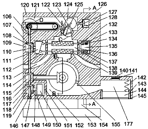
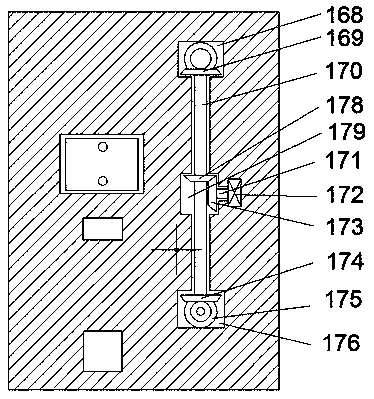
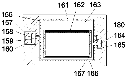
[0019] Combine below Figure 1-5 The present invention is described in detail, wherein, for the convenience of description, the orientations mentioned below are now defined as follows: figure 1 The projection relationship of itself is the same as the up, down, left, right, front, and rear directions.

[0020] refer to Figure 1-5 , a method of using cement grinding equipment for cement grinding of the present invention, wherein a cement grinding equipment includes a body 120 and a crushing cavity 121 arranged in the body 120 and extending left and right. The crushing cavity 121 The right side is provided with a first gear meshing cavity 168 extending back and forth, the crushing cavity 121 is provided with a cement crushing component, the cement crushing component is rotatably connected to a first rotating shaft 126, and the first rotating shaft 126 rotates and cooperates A first power assembly is connected, a cement conveying cavity 100 extending left and right is arranged ...


PUM


Abstract

The invention discloses a method for conducting cement grinding through cement grinding equipment. The cement grinding equipment comprises an equipment body and a smashing cavity formed in the equipment body and extending in a left-right direction, wherein a first gear engagement cavity extending in a front-back direction is formed in the right side of the smashing cavity, a cement smashing assembly is arranged in the smashing cavity, and connected with a first rotating shaft in a rotating fit mode, the first rotating shaft is connected with a first power assembly in the rotating fit mode, a cement conveying cavity extending in the left-right direction is formed in the lower portion of the smashing cavity, a cement conveying device is arranged in the cement conveying cavity and connected with a second power assembly in the rotating fit mode, And a communicating cement screening cavity extending in the left-right direction is formed in the lower side of the smashing cavity. The cement grinding equipment is simple in structure and convenient to use, and by adopting the integral design of the equipment body, automatic adjusting for the processes such as pre-smashing of cement, furtherscreening of the cement and final grinding forming of the cement is achieved in the equipment body.

Description

technical field [0001] The invention relates to the technical field of non-metal processing, in particular to a method for cement grinding by utilizing cement grinding equipment. Background technique [0002] With the improvement of the domestic economy and the rapid development of the construction industry, the demand for cement has greatly increased. As we all know, cement grinding is the final process of cement manufacturing, and it is also the most power-consuming process. The particle size of the grinding ultimately determines whether the comprehensive performance of cement is It can meet the requirements of hydration area, hydration rate, cement paste coagulation and hardening. However, the comprehensive power consumption of large-scale cement grinding equipment has remained high for a long time, the energy consumption is huge, and the cost of cement is high. At the same time, small and medium-sized self-made mechanical equipment is not only inefficient, but also pollu...

Claims


Application Information

Patent Timeline
IPC IPC(8): C04B7/52
CPCC04B7/52C04B7/522
Inventor 余芳珺
Owner 余芳珺
Why Eureka
Eureka Blog
Learn More