[0033] The embodiment of the present application provides a real-time detection and processing system for embossing in a nail rolling section.
[0034] In order to make those skilled in the art better understand the technical solutions in the present application, the technical solutions in the embodiments of the present application will be described clearly and completely below with reference to the accompanying drawings in the embodiments of the present application. Obviously, the described The embodiments are only a part of the embodiments of the present application, but not all of the embodiments. Based on the embodiments in this application, all other embodiments obtained by those of ordinary skill in the art without creative work shall fall within the scope of protection of this application.
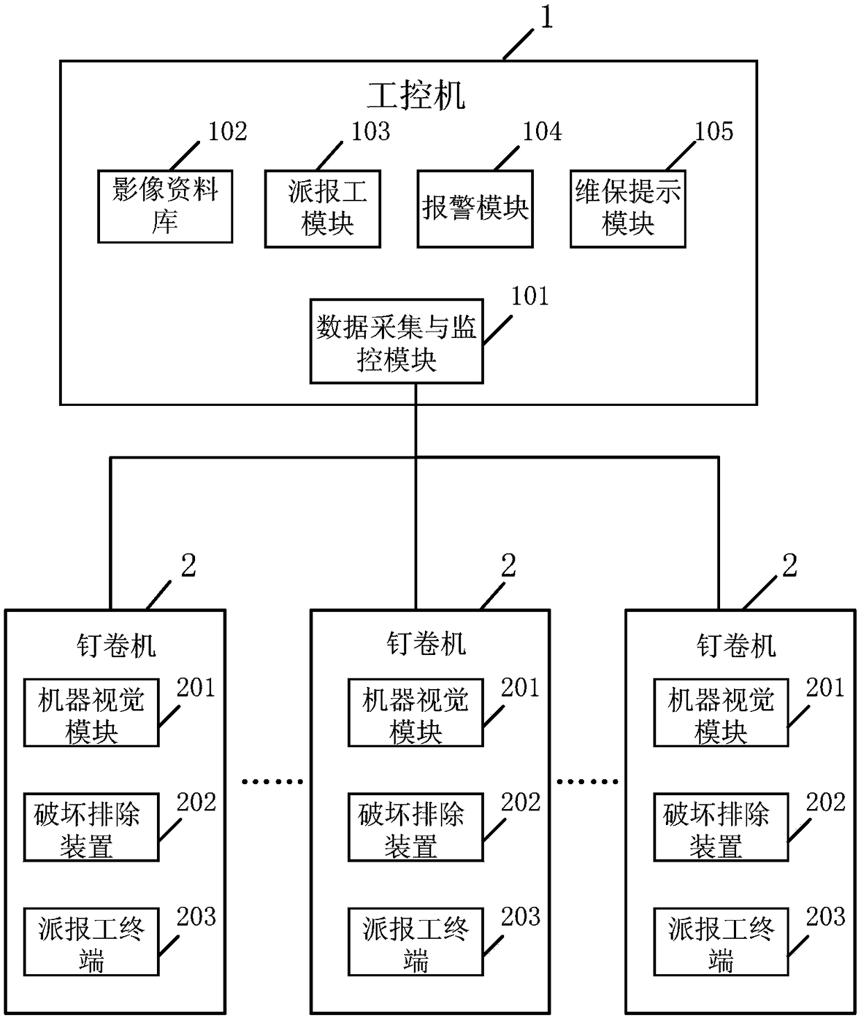
[0035] figure 1 It is a schematic structural diagram of a module of a real-time detection and processing system for embossing in a nail roll section provided by an embodiment of the present application. Although the present application provides the device structure as shown in the following embodiments or drawings, more or less units may be included in the method or device based on routine or without inventive effort. In a structure that does not logically have a necessary causal relationship, the structures of these devices are not limited to the structures shown in the embodiments of the present application or the drawings.
[0036] Specifically, as figure 1 As mentioned, an embodiment of a real-time detection and processing system for embossing in a nail roll section provided by the present application may include:
[0037] The machine vision module 201, each nail rolling machine 2 is equipped with one of the visual recognition modules 201, which is used for online real-time acquisition of the petal patterns formed by each embossing of the positive foil and the negative foil of the nail rolling section, and according to the petals. Real-time detection of whether each embossing is qualified on the pattern line, wherein the number of the nail rolling machines is greater than or equal to 1;
[0038] The industrial computer 1 includes a data acquisition and monitoring module 101 for establishing a data interactive connection with the machine vision module 201, for obtaining the embossing detection result of each embossing in real time, and for sending the response of the industrial computer 1 Control instructions based on the embossing detection results, and petal patterns for receiving unqualified embossing products;
[0039] The industrial computer 1 further includes an image database 102 for storing the petal patterns of the unqualified products for embossing.
[0040] The machine vision module 201 has a storage medium, stores a pre-trained image recognition model, inputs the petal pattern formed by each embossing into the image recognition model, and outputs the petal formed by each embossing. The test result of whether the pattern is qualified or not.
[0041] In this example, the number of the machine vision modules 201 matches the number of the nail rolling machines 2, each machine vision module 201 is responsible for the embossing detection of one nail rolling machine 2, and a plurality of machine vision modules 201 The embossing detection result of each embossing of the loaded nail rolling machine is uploaded to the industrial computer 1 in real time. The embossing test results are qualified and unqualified for embossing.
[0042] In this example, the system further includes an elimination and destruction device 202, which is arranged at the nail rolling machine 2 and is connected to the data acquisition and monitoring module 101;
[0043]When the machine vision module 201 detects that a certain embossing is unqualified, upload the embossing detection result of the unqualified embossing to the data collection and monitoring module 101;
[0044] The industrial computer 1 generates a control instruction for eliminating damage, and the data acquisition and monitoring module 101 sends it to the eliminating damage device 202. When the eliminating damage device 202 receives the control instruction, the embossing will not be processed for this time. Elimination of damage to qualified products;
[0045] The machine vision module 201 is also used to upload the petal pattern corresponding to the unqualified embossing to the data acquisition and monitoring module 101, and the industrial computer 1 stores the petal pattern corresponding to the unqualified embossing to the data collection and monitoring module 101. The image database 102 is described.
[0046] Wherein, the elimination and destruction device 202 includes:
[0047] Clamping mechanism 2021, used to clamp unqualified nail roll products;
[0048] Destruction mechanism 2022, for destroying the unqualified nail roll products with embossing;
[0049] The collection box 2023 is used for collecting the damaged staple roll products.
[0050] Of course, the eliminating and destroying device 202 has a corresponding electronic control device, which is used for executing the elimination and destruction of defective products according to the control instruction sent by the industrial computer 1 . Specifically, when the industrial computer 1 obtains that the embossing detection result is that the embossing is unqualified, the industrial computer 1 sends a destruction removal instruction to the electronic control device of the removal and destruction device 202, and the electronic control device The clamping mechanism 2021 is controlled to take out the finished product of the nail roll corresponding to this embossing, and then the destruction mechanism 2022 is controlled to destroy the product, and the product can be flattened to distinguish it from the embossed qualified product, This product is then placed in the collection box 2023.
[0051] figure 2 It is a schematic diagram of the device structure of the foil guiding mechanism and the machine vision module provided by an embodiment of the present application. like figure 2 As shown, in this example, the machine vision module 201 includes a ring light source 2011, a camera 2012, an image recognition module 2013, and a foil guiding mechanism 2014;
[0052] The foil drawing mechanism 2014 is used to draw out the positive and negative foils embossed by the staple rolling machine 2, so that the petal pattern formed by the embossing is located within the shooting range of the camera 2012, and the ring light source 2011 is used to illuminate For the positive foil and the negative foil, the camera is used to photograph the petal patterns on the positive foil and the negative foil under the illumination of the ring light source 2011 . The camera 2012 includes two lenses, and the two lenses are respectively directed toward the positive foil and the negative foil within the illumination range, for acquiring the petal pattern. The two lenses are respectively used to obtain the petal pattern formed by positive foil embossing and the petal pattern formed by negative foil embossing. The distance and angle between the ring light source 2011 and the negative foil are adjusted to preset values, and the light source parameters of the ring light source 2011 are adjusted to preset values. The brightness, color, and color temperature of the light source are all adjusted to preset values that can make the petal pattern clearer.
[0053] like figure 2 As shown, guide pins are nailed on the positive foil and the negative foil through an embossing process, and the petal pattern is located where the guide pins are located.
[0054] The image recognition module 2013 stores a pre-trained image recognition model, which is used to determine whether the embossing corresponding to the petal pattern is qualified by using the image recognition model.
[0055] Since the space for embossing of the existing nail rolling machine 2 is often small, the machine vision module cannot be installed. Therefore, in this example, a corresponding foil lead mechanism 2014 is provided, which is used to lead the positive foil and the negative foil to a position with a large space, which is convenient for the installation of the machine vision module.
[0056] like figure 2 As shown, the foil guiding mechanism 2014 may include three rollers, by which the embossed positive foil and negative foil can be transferred to the position facing the ring light source 2011, the ring light source 2011 is penetrating in the middle, from all The light reflected from the petal pattern on the positive or negative foil is transmitted to the lens of the camera 2012 through the through hole in the middle of the ring light source 2011, and the camera 2012 captures the petal pattern on the positive foil and the negative foil. Then, the image recognition module 2014 determines whether the corresponding embossing is qualified according to the petal pattern.
[0057] image 3 It is a schematic diagram of the device structure of the foil guiding mechanism and the machine vision module provided by another embodiment of the present application. like image 3 As shown, the foil guiding mechanism 2014 includes five rollers. In order to adapt to different actual inspection environments, the implementer can adjust the number of rollers as required, so that the machine vision module 201 can work effectively.
[0058] In an embodiment of the present application, the camera 2012 has dual lenses, and the two lenses are respectively used to acquire the petal pattern formed on the positive electrode aluminum foil and the petal pattern formed on the negative electrode aluminum foil. The positive electrode aluminum foil nail has a positive electrode guide pin, and the negative electrode aluminum foil nail has a negative electrode guide pin.
[0059] like figure 1 As mentioned, in an embodiment of the present application, the system further includes a defective product elimination and destruction mechanism 104, which is arranged after the nail rolling machine 101 and is controlled by the industrial computer 102, and is used for rolling the nails that are not qualified for embossing. The finished product is excluded and destroyed. Figure 4 It is a schematic diagram of the device structure of the defective product elimination and destruction mechanism provided by an embodiment of the present application.
[0060] In this example, the industrial computer 1 further includes an alarm module 104. Correspondingly, the industrial computer 1 is also used to calculate the unqualified embossing rate of each nail rolling machine 2. When the unqualified embossing rate is When the preset value is exceeded, the industrial computer 1 controls the alarm module to generate alarm information for prompting machine maintenance and adjustment, and is used to control the staple rolling machine 2 to stop running and wait for inspection and maintenance. Among them, each nail rolling machine 2 is controlled by a PLC controller, and the industrial computer 1 is signal-connected with the PLC controller of each nail rolling machine 2, and the corresponding control instructions are sent through the PLC controller, so as to realize the control of each nail rolling machine 2. Remote control of table nail rolling machine 2.
[0061] After receiving the alarm, the staff will overhaul the nail rolling machine 2 . System faults can be eliminated in a timely and effective manner to avoid waste of resources caused by blind production.
[0062] like figure 1 As mentioned, in an embodiment of the present application, the industrial computer 1 further includes a dispatcher module 103, and correspondingly, each nail rolling machine 2 is provided with a dispatcher that has a data connection with the dispatcher module 103. The dispatcher module 103 is used to issue a work order to the dispatcher terminal 203, and to obtain the production quantity and operating status information of each nail rolling machine, and to use the operation according to the operation The status information sends a machine maintenance prompt to the dispatcher terminal 203 . The operating status information includes machine operating parameters such as the voltage, current, and normal operation of the nailing machine. If the operating status is abnormal, or the production quantity is abnormal, the dispatching module 103 will send the dispatching terminal to the dispatching terminal in real time. 203 Issue a reminder to repair the machine.
[0063] Wherein, the reporting includes the starting of the process, that is, when the nailing machine 2 starts to work, the starting time is recorded and uploaded through the reporting terminal 203 . It also includes reporting the work at the end of the process, that is, when the nailing machine 2 ends the work, the terminal 203 for dispatching workers records and uploads the relevant dispatching information at the end of the work.
[0064] The content of the work report at least includes the time when the process starts and ends, the number of completed processes at the end of the process, the number of qualified nail rolls, the number of scrapped, and the number of repairs. The job reporting can be performed by a specific staff member through the job reporting terminal, and uploaded to the industrial computer 1 . The industrial computer 1 has a display component, which can display the dispatching information of each corresponding nail rolling machine 2 .
[0065] The job reporting terminal can support at least three reporting methods, and can report jobs manually, or through barcodes, or through an APP installed in a mobile electronic device.
[0066] In this example, as figure 1 As shown, the industrial computer 1 further includes a maintenance prompt module 105, and the industrial computer 1 is also used to record the maintenance time of each nail rolling machine 2. When the nail rolling machine 2 is not maintained and maintained When the time exceeds the maintenance period, the maintenance prompt module 105 generates maintenance prompt information for prompting maintenance of the staple rolling machine 2 .
[0067] Using the implementation of the real-time detection and processing system for embossing in the nail-rolling section provided by the above embodiments, the embossing detection result can be automatically determined by machine vision, the comprehensive real-time detection of the embossing process can be realized online, and the efficiency of the embossing detection can be improved. Reliability, comprehensiveness and timeliness. It can also effectively exclude the influence of human factors and improve the detection accuracy. Moreover, the industrial computer can record the number of unqualified embossing in real time according to the test results, and take corresponding measures, which can completely eliminate unqualified products, and can also timely alarm and eliminate machine equipment failures. In addition, through the data acquisition and monitoring module (SCADA), the data interaction between the industrial computer and multiple nail rolling machines can be realized, and the remote monitoring and control of the nail rolling machines can be realized. Through the dispatching module, the production of each nail rolling machine and the maintenance prompt of the machine can be reasonably allocated or adjusted. Through the maintenance prompt module, it can effectively ensure that the nail rolling machine is regularly repaired and maintained.
[0068] The devices or modules described in the above embodiments may be specifically implemented by computer chips or entities, or by products with certain functions. For the convenience of description, when describing the above device, the functions are divided into various modules and described respectively. Of course, when implementing the present application, the functions of each module can be implemented in the same one or more software and/or hardware, and the modules that implement the same function can also be implemented by a combination of multiple sub-modules. The apparatus embodiments described above are only illustrative. For example, the division of the modules is only a logical function division. In actual implementation, there may be other division methods. For example, multiple modules or components may be combined or integrated. to another system, or some features can be ignored, or not implemented.
[0069] The application may be described in the general context of computer-executable instructions, such as program modules, being executed by a computer. Generally, program modules include routines, programs, objects, components, data structures, classes, etc. that perform particular tasks or implement particular abstract data types. The application may also be practiced in distributed computing environments where tasks are performed by remote processing devices that are linked through a communications network. In a distributed computing environment, program modules may be located in both local and remote computer storage media including storage devices.
[0070] From the description of the above embodiments, those skilled in the art can clearly understand that the present application can be implemented by means of software plus a necessary general hardware platform. Based on this understanding, the technical solutions of the present application can be embodied in the form of software products in essence or the parts that make contributions to the prior art, and the computer software products can be stored in storage media, such as ROM/RAM, magnetic disks , CD, etc., including several instructions to make a computer device (which may be a personal computer, a mobile terminal, a server, or a network device, etc.) execute the methods described in various embodiments or some parts of the embodiments of the present application.
[0071] The various embodiments in this specification are described in a progressive manner, and the same or similar parts between the various embodiments may be referred to each other, and each embodiment focuses on the differences from other embodiments. The present application may be used in numerous general purpose or special purpose computer system environments or configurations. For example: personal computers, server computers, handheld or portable devices, tablet devices, multiprocessor systems, microprocessor-based systems, set-top boxes, programmable electronics, network PCs, minicomputers, mainframe computers, including the above Distributed computing environment of any system or device, etc.
[0072] Although the application has been described by way of examples, those of ordinary skill in the art will recognize that the application is subject to many modifications and changes without departing from the spirit of the application, and it is intended that the appended claims include such modifications and changes without departing from the spirit of the application.