Photoresist stripping apparatus and stripping method thereof
A technology for stripping equipment and photoresist, which is applied in the field of photoresist stripping equipment and photoresist stripping, can solve the problems of silicon source loss and other problems, achieve the effects of reducing silicon loss, reducing residues and volatiles, and prolonging waiting time
- Summary
- Abstract
- Description
- Claims
- Application Information
AI Technical Summary
Problems solved by technology
Method used
Image
Examples
no. 1 example
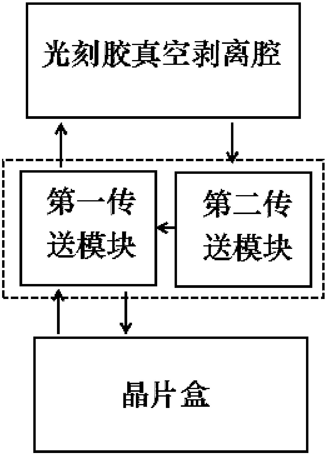
[0032] The first embodiment of the photoresist stripping equipment provided by the present invention includes: a photoresist vacuum stripping chamber, a first transfer module, a second transfer module and a wafer box;
[0033] The wafer without photoresist stripping is sent from the wafer cassette to the first transfer module, and then sent into the photoresist vacuum stripping chamber by the first transfer module, and the photoresist stripping is carried out on the wafer in the photoresist vacuum stripping chamber, and the photoresist is peeled off. The wafers are transported by the second transfer module to the first transfer module and then transferred to the wafer box for storage;
[0034] Wherein, the first transmission module can balance the second transmission module and the external air pressure, the second transmission module is a non-vacuum environment, the internal pressure of the second transmission module has a pressure difference from the external air pressure, an...
no. 2 example
[0035] The second embodiment of the photoresist stripping equipment provided by the present invention, the second embodiment of the photoresist stripping equipment provided by the present invention, includes: a photoresist vacuum stripping chamber, a first transfer module, a second transfer module and a wafer cassette;
[0036] The wafer without photoresist stripping is sent from the wafer cassette to the first transfer module, and then sent into the photoresist vacuum stripping chamber by the first transfer module, and the photoresist stripping is carried out on the wafer in the photoresist vacuum stripping chamber, and the photoresist is peeled off. The wafers are transported by the second transfer module to the first transfer module and then transferred to the wafer box for storage;
[0037] Wherein, the first transmission module can balance the second transmission module and the external air pressure, the second transmission module is a non-vacuum environment, the internal ...
no. 3 example
[0038] The third embodiment of the photoresist stripping equipment provided by the present invention includes: a photoresist vacuum stripping chamber, a first transfer module, a second transfer module and a wafer box;
[0039] The wafer without photoresist stripping is sent from the wafer cassette to the first transfer module, and then sent into the photoresist vacuum stripping chamber by the first transfer module, and the photoresist stripping is carried out on the wafer in the photoresist vacuum stripping chamber, and the photoresist is peeled off. The wafers are transported by the second transfer module to the first transfer module and then transferred to the wafer box for storage;
[0040]Wherein, the first transmission module can balance the second transmission module and the external air pressure, the second transmission module is a non-vacuum environment, the internal pressure of the second transmission module has a pressure difference from the external air pressure, and...
PUM
 Abstract
Description
Claims
Application Information
 - R&D
- Intellectual Property
- Life Sciences
- Materials
- Tech Scout
- Unparalleled Data Quality
- Higher Quality Content
- 60% Fewer Hallucinations
Browse by: Latest US Patents, China's latest patents, Technical Efficacy Thesaurus, Application Domain, Technology Topic, Popular Technical Reports.
© 2025 PatSnap. All rights reserved.Legal|Privacy policy|Modern Slavery Act Transparency Statement|Sitemap|About US| Contact US: help@patsnap.com

