Field reseeding tool

A tool and field technology, applied in the field of field replanting tools, can solve the problems of physical exertion, slow replanting speed, low efficiency, etc., and achieve the effect of reducing labor intensity, convenient use, and ensuring growth safety.

Pending Publication Date: 2019-01-25
王芳
View PDF0 Cites 1 Cited by
  • Summary
  • Abstract
  • Description
  • Claims
  • Application Information

AI Technical Summary

Problems solved by technology

Because the area lacking seedlings is relatively small and scattered, it is impossible to sow it with a seeder. Usually, replanting is done manually. Soil is enough, the whole process is a lot of operations, the work needs to keep squatting and lifting, which consumes a lot of energy, and the speed of replanting is slow and the efficiency is low

Method used


Image

  • Field reseeding tool
  • Field reseeding tool
  • Field reseeding tool

Examples


Embodiment 1

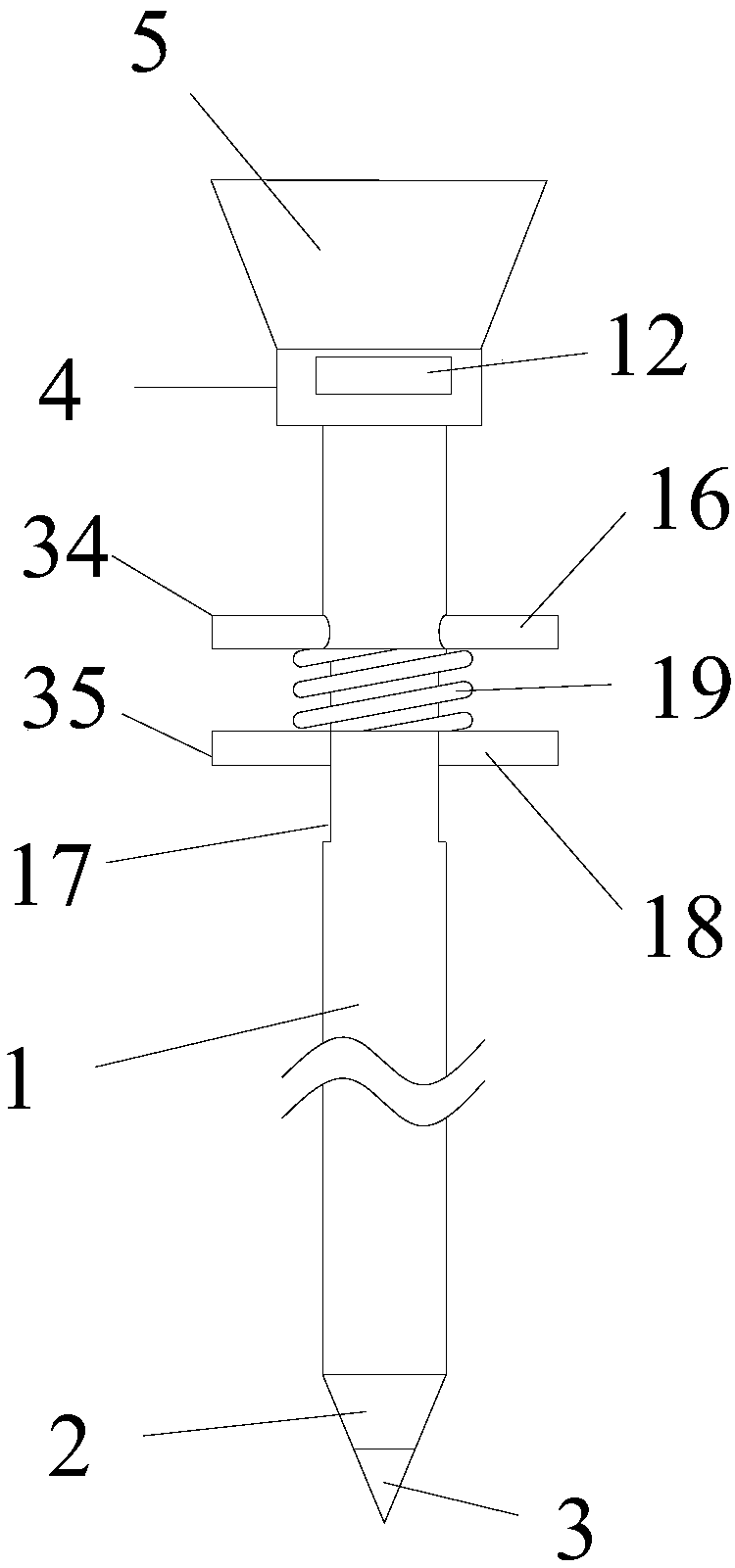
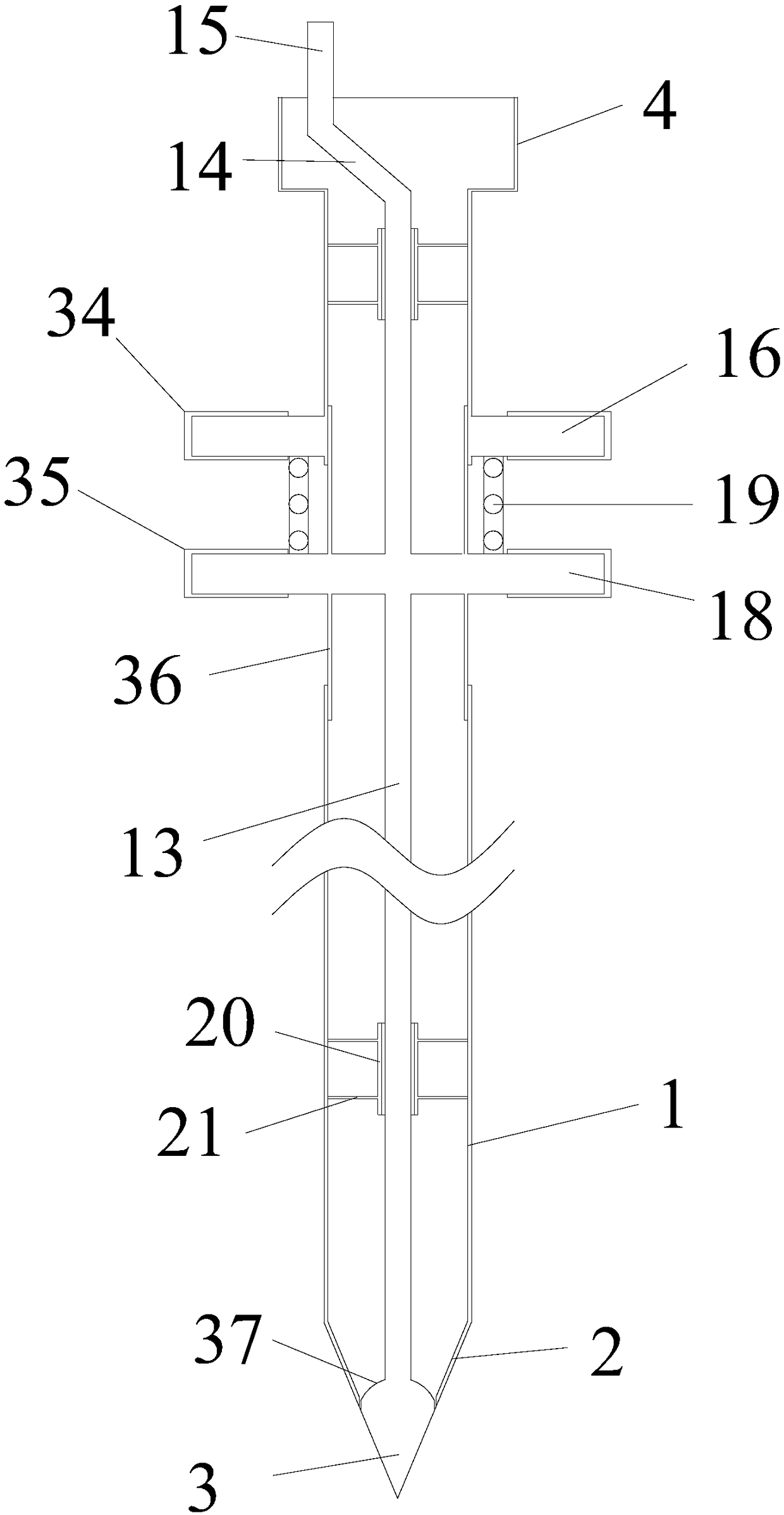
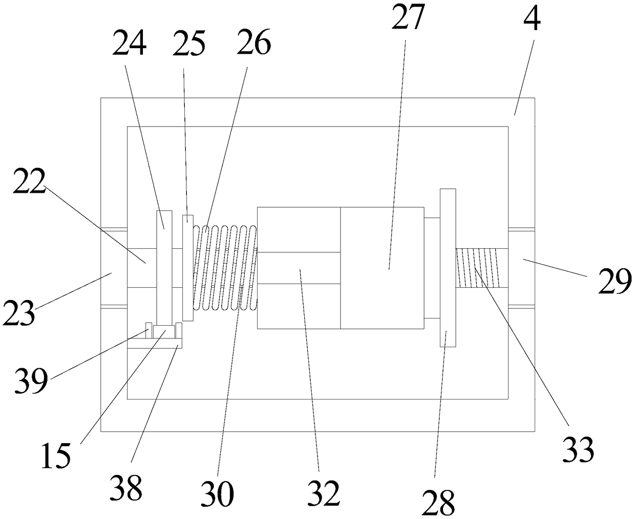
[0032] like Figure 1-7As shown, the field replanting tool according to the embodiment of the present invention includes a planting cylinder 1, a frustum shell 2 is provided on the bottom surface of the planting cylinder 1, and a conical drill bit 3 is provided on the bottom surface of the cone shell 2. The top surface of the seed cylinder 1 is provided with a support platform 4, and the top surface of the support platform 4 is provided with a seed hopper 5, and the side of the seed hopper 5 and the edge of the top surface of the support platform 4 are provided with a support rod 6. The bottom surface of the next seed hopper 5 is provided with a rectangular discharge port 7, and the opposite sides of the rectangular discharge port 7 are provided with a circular through hole 8, and one of the circular through hole 8 sides is provided with a circular groove 9, so that The inside of the circular groove 9 is provided with an annular baffle 10 corresponding to it, and the inner cir...

Embodiment 2

[0044] The difference from Example 1 is that, if Figure 8 and Figure 9 As shown, the reset member in this embodiment is a reset elastic sleeve 40, which is a plastic elastic sleeve, and the top of the reset elastic sleeve 40 extends outward to form an upper flange 41, which is close to the bottom of the fixed handle 16 , the plastic layer one 34 is sleeved on the periphery of the upper flange 41 . The bottom of reset elastic sleeve 40 extends outwards to form lower flange 42, lower flange 42 is close to the top of movable handle 18, plastic layer 2 35 is socketed on the periphery of lower flange 42, upper flange 41 and lower flange 42 The radial lengths are equal to A, and A is between 10mm-40mm, which can prevent soil and the like from entering the reset elastic sleeve 40, so as to affect the elastic reset effect of the reset elastic sleeve 40. In order to continuously maintain the elastic reset effect of the reset elastic sleeve 40, an elastic member is embedded around t...


PUM


Abstract

The invention discloses a field reseeding tool, which comprises a seeding cylinder, wherein the bottom surface of the seeding cylinder is provided with a round table shell and a conical drill bit, thetop surface of the seeding cylinder is provided with a support table, the top surface of the support table is provided with a seeding hopper, the side face of the seeding hopper is provided with a support rod arranged at the edge of the top surface of the support table, the bottom face of the seeding hopper is provided with a rectangular discharge port, the opposite side faces of the rectangulardischarge port are provided with round through holes, the side face of one round through hole is provided with a round groove, the round groove is internally provided with an annular baffle fitting thereto, the inner round side face of the annular baffle is provided with a stop block, a seeding adjustment device is penetrated between the corresponding round through hole and the annular baffle, theseeding adjustment device is fixed on the side wall of the support table, the top end of the cone drill bit is provided with a support column located in the seeding cylinder, the top end of the support column is provided with a correcting rod, and the top end of the correcting rod is provided with a straight rack. The field reseeding tool greatly improves the reseeding speed and efficiency of a laborer.

Description

technical field [0001] The invention relates to the field of agricultural machinery, in particular to a field replanting tool. Background technique [0002] When the crops are just sprouting, we often see the phenomenon of lack of seedlings. Farmers solve the phenomenon of lack of seedlings by replanting crop seeds. Because the area lacking seedlings is relatively small and scattered, it is impossible to sow it with a seeder. Usually, replanting is done manually. Soil is enough, the whole process is a lot of operations, and the work needs to keep squatting and lifting, which consumes a lot of energy, and the speed of replanting is slow and the efficiency is low. [0003] Aiming at the problems in the related technologies, no effective solution has been proposed yet. Contents of the invention [0004] Aiming at the problems in the related art, the present invention proposes a field replanting tool to overcome the above-mentioned technical problems existing in the related ...

Claims


Application Information

Patent Timeline
Patent Type & Authority Applications(China)
IPC IPC(8): A01C7/02A01C7/20
CPCA01C7/02A01C7/20
Inventor 王芳
Owner 王芳
Why Eureka
Try Eureka