Angle sensor for leg angle measurement

An angle sensor, angle measurement technology, applied in the direction of sensor, diagnostic record/measurement, application, etc., can solve the problem of inaccurate angle change, interference of measurement results, error, etc., to achieve accurate angle value, eliminate environmental interference, and improve accuracy Effect

Inactive Publication Date: 2019-01-25
华蓥市铜堡初级中学
View PDF13 Cites 1 Cited by
  • Summary
  • Abstract
  • Description
  • Claims
  • Application Information

AI Technical Summary

Problems solved by technology

[0004] The object of the present invention is to provide an angle sensor for leg angle measurement, which solves the inaccurate observation of leg angle changes with the naked eye and the impact of ambient temperature and strong magnetic

Method used


Image

  • Angle sensor for leg angle measurement
  • Angle sensor for leg angle measurement

Examples


Embodiment 1

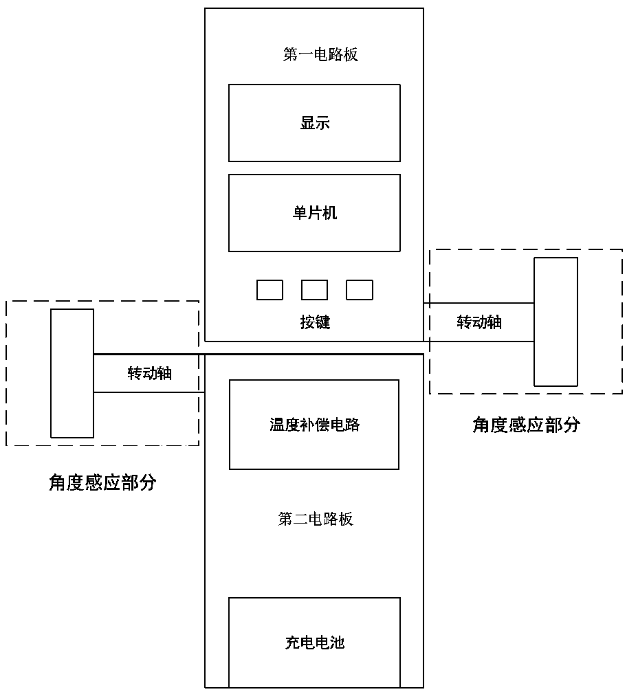
[0034] Such as figure 1 , in the application of leg correction, an angle sensor for leg angle measurement includes a first circuit board: used to generate a first angle signal and a first temperature signal at the thigh, and combine the first angle signal and the second temperature signal A temperature signal is passed to the single-chip microcomputer; the second circuit board: used to generate the second angle signal and the second temperature signal at the shank, and pass the second angle signal and the second temperature signal to the single-chip microcomputer; the single-chip microcomputer: used to process the first The angle signal, the second angle signal, the first temperature signal, and the second temperature signal to obtain the final angle value. Each of the first circuit board and the second circuit board includes an angle sensing part connected to the single chip microcomputer for sensing the angle of the leg. It also includes a temperature compensation circuit c...


PUM


Abstract

An angle sensor for leg angle measurement is disclosed and belongs to the field of an angle sensor. The angle sensor includes a first circuit board for generating a first angle signal and a first temperature signal at the thigh and transmitting the first angle signal and the first temperature signal to the single chip microcomputer, a second circuit board for generating a second angle signal and asecond temperature signal at the lower leg and transmitting the second angle signal and the second temperature signal to a single chip microcomputer, and the single chip microcomputer for processingthe first angle signal, the second angle signal, the first temperature signal and the second temperature signal to obtain a final angle value of the single chip microcomputer. It solves the problems of inaccurate observation of angle change of leg shape by naked eyes, interference of ambient temperature and strong magnetic field in leg shape correction, dance training and rehabilitation treatment,and can be used in leg shape correction, dance training and rehabilitation treatment.

Description

technical field [0001] The invention provides an angle sensor for leg angle measurement, which belongs to the field of angle sensors. Background technique [0002] Existing angle sensors, such as contact potentiometers, calculate the corresponding movement of the rotating shaft by detecting the voltage change in the circuit caused by the sliding of the potentiometer connected to the rotating shaft. The principle is simple, but the precision of the potentiometer will decrease or even fail completely after the resistance body is worn out after a long period of sliding friction. In addition, there is another situation that is a magnetic position sensor, which uses the rotation of a permanent magnet to generate a rotating magnetic field, and then detects the direction of the magnetic field through a magnetic position sensor chip, thereby detecting the rotation angle. However, there is also a problem with this structure. The magnetic position sensor chip cannot work in a strong ...

Claims


Application Information

Patent Timeline
IPC IPC(8): A61B5/107
CPCA61B5/1071A61B5/1075
Inventor 邓华
Owner 华蓥市铜堡初级中学
Why Eureka
Try Eureka