
Multi-rotor forced mixer

A powerful mixer and multi-rotor technology, applied in mixers, mixers with rotating mixing devices, mixer accessories, etc., can solve the problems of decreased machine running stability, poor mixing uniformity, and increased machine noise, etc. To achieve the effect of improving stability, good vibration resistance, and prolonging life

Active Publication Date: 2019-01-25
江阴市创裕机械有限公司
View PDF9 Cites 0 Cited by
  • Summary
  • Abstract
  • Description
  • Claims
  • Application Information

AI Technical Summary

Problems solved by technology

[0005] First, because the cylinder is fixed and there is only one rotor assembly in the cylinder, the material can only move in one direction, resulting in low mixing efficiency and poor mixing uniformity
[0006] The second is that the existing vertical mixer adopts a cantilever beam structure, and the driving mechanism for driving the rotor assembly to rotate is arranged on the cantilever beam. When working, the rotor assembly rotates to form a strong stirring effect on the material, and the rotor assembly is subjected to the reaction of the material. The large force will easily cause the vibration of the cantilever beam, which will reduce the stability of the machine operation and increase the noise of the machine during work.
[0007] The third is that the discharge door for the mixer is opened or closed manually or semi-automatically, and its degree of automation is relatively low

Method used


Image

  • Multi-rotor forced mixer
  • Multi-rotor forced mixer
  • Multi-rotor forced mixer

Examples


Embodiment Construction

[0069] The specific implementation manners of the present invention will be further described below in conjunction with the drawings and examples. The following examples are only used to illustrate the technical solution of the present invention more clearly, but not to limit the protection scope of the present invention.

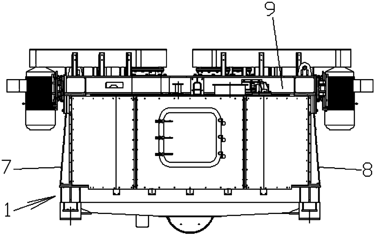
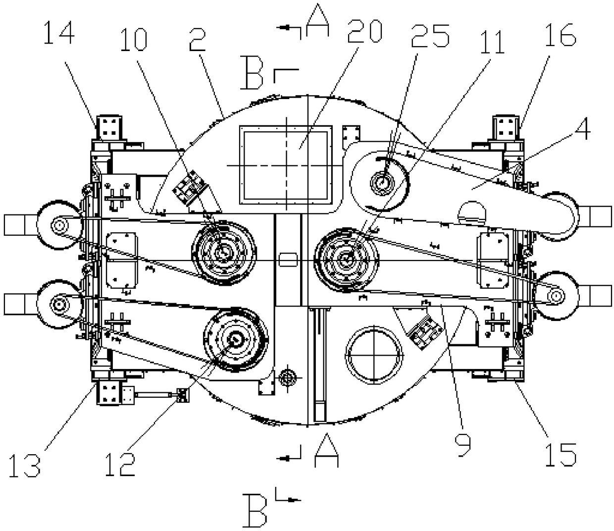
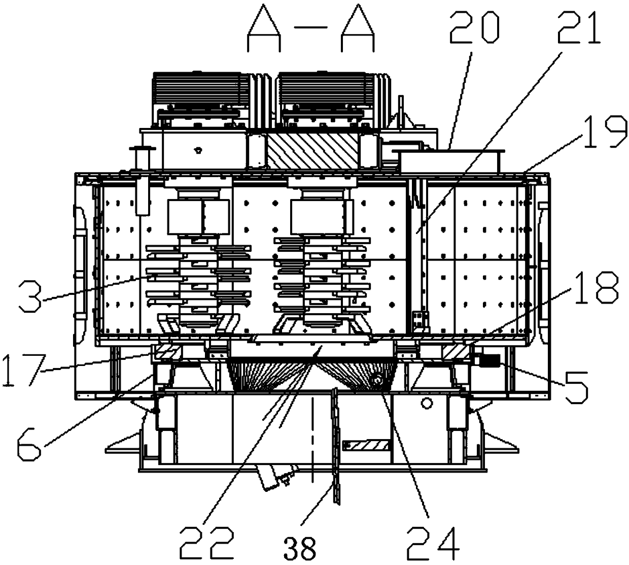
[0070] Such as Figures 1 to 13 Shown is an embodiment of a multi-rotor intensive mixer of the present invention, including a frame 1, a cylinder 2 arranged on the frame 1 for placing mixed materials, and a cylinder 2 arranged on the cylinder 2, the rotor assembly 3 for mixing materials, and the rotor drive mechanism 4 and the cylinder drive mechanism 5 arranged on the frame 1 for respectively connecting and driving the rotor assembly 3 and the cylinder 2 to realize rotation, The frame 1 includes a bottom frame 6, a left column module 7 and a right column module 8 that are respectively arranged on both sides of the bottom frame 6 and extend upward, and are...


PUM


Abstract

The invention relates to the technical field of mixing machinery and discloses a multi-rotor forced mixer which comprises a rack, a cylinder, at least two rotor components, a rotor drive mechanism anda cylinder drive mechanism; the rotor drive mechanism and the cylinder drive mechanism are used for being connected with and driving the rotor components and the cylinder to realize rotation respectively; the rack comprises a bottom seat frame, a left upright column module, a right upright column module and a beam; the left upright column module and the right upright column module are arranged onportions of the two sides of the bottom seat frame respectively; the beam is connected with the upper end of the left upright column module and the upper end of the right upright column module; the cylinder is rotationally arranged on the bottom seat frame; the rotor drive mechanism is arranged on the beam of the rack; the cylinder drive mechanism is arranged on the bottom seat frame; the bottomof the rack is installed on an automatic discharging device with a weighing sensor; and the automatic discharging device comprises a discharging door used for opening or closing a discharging hole. The multi-rotor forced mixer improves the efficiency and the uniformity of material mixing and is good in smoothness of equipment running and high in discharging automation degree.

Description

technical field [0001] The invention relates to the technical field of mixing machinery, in particular to a multi-rotor intensive mixer. Background technique [0002] A mixer is a mechanical device that uses mechanical force and gravity to evenly mix two or more materials. Widely used in chemical, petrochemical, pharmaceutical, food, building materials, mining and metallurgy, environmental protection, printing and dyeing, ceramics, rubber, plastics and other fields. [0003] In the prior art, a typical mixer includes a fixed cylinder, the upper part of the cylinder is provided with a feed port, the lower part is provided with a discharge port, and a rotor assembly for mixing materials is provided in the cylinder. When mixing materials, the rotor (stirring blade) on the rotor assembly rotates, and the materials are mixed under the action of the rotor. After the material is mixed, it needs to be discharged from the internal container of the equipment. Usually, an active disc...

Claims


Application Information

Patent Timeline
Patent Type & Authority Applications(China)
IPC IPC(8): B01F7/04B01F15/00B01F15/02
CPCB01F27/092B01F27/701B01F27/2322B01F27/191B01F35/43B01F35/714
Inventor 魏宏飚
Owner 江阴市创裕机械有限公司
Learn More