Production mold of prefabricated stacking floor slab
A technology for superimposing floor slabs and moulds, which is applied in the direction of moulds, etc., can solve the problems of high mold removal resistance, low mold processing efficiency, and difficulty in plugging grout leakage at rib outlet grooves, so as to achieve high processing efficiency and reduce the amount of grout leakage Effect
- Summary
- Abstract
- Description
- Claims
- Application Information
AI Technical Summary
Problems solved by technology
Method used
Image
Examples
Embodiment 1
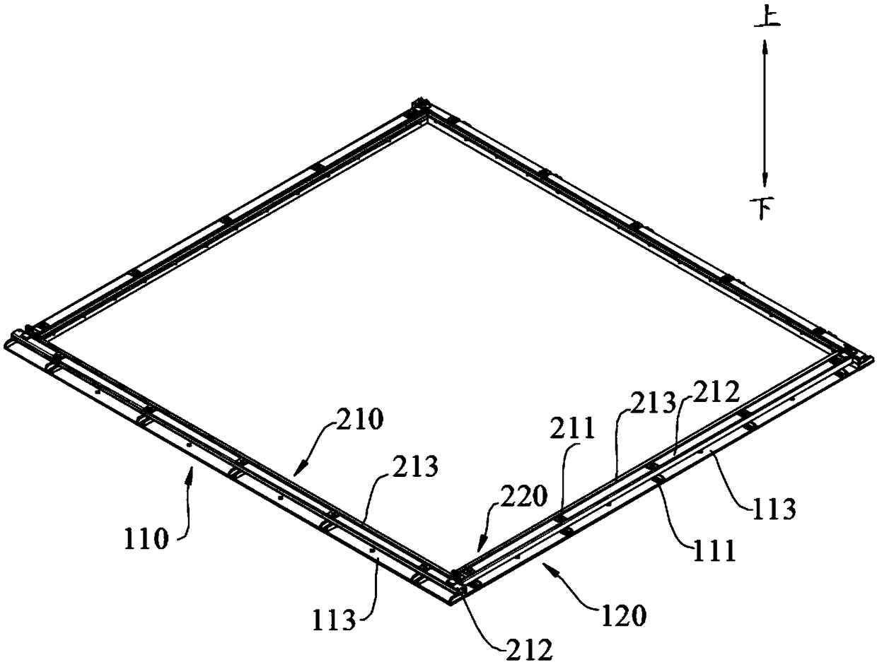
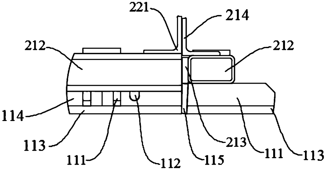
[0024] refer to Figure 1 to Figure 3 , this embodiment provides a production mold for prefabricated laminated floors, including a lower mold 100 and an upper mold 200 . The lower mold 100 includes two first side molds 110 arranged symmetrically and two second side molds 120 arranged symmetrically. Both ends of the first side molds 110 are vertically connected to the second side molds 120 respectively. The first side mold 110 includes a bearing part 111 which is in contact with the upper mold 200 and carries the upper mold 200 , and a bead groove 112 provided on the side of the first side mold 110 . The second side mold 120 includes a bearing part 111 which is in contact with the upper mold 200 and carries the upper mold 200 , and a bead groove 112 provided on the side of the second side mold 120 . The rib groove 112 is matched with the steel bar size of the prefabricated laminated floor slab. The bearing parts 111 and the rib outlet grooves 112 are alternately arranged. Th...
Embodiment 2
[0033] This embodiment provides a production mold for prefabricated laminated floor slabs. Its structure is basically the same as that of Embodiment 1, the difference is that the rib groove 112 is semicircular, and the second side plate 213 has a first groove (not shown) shown), the first groove is arranged on the bottom surface of the second side plate 213 and is semicircular, and the radius of the first groove is equal to the radius of the groove 112; when the upper mold 200 and the lower mold 100 are installed, the first The opening of the groove is relatively matched with the opening of the rib outlet groove 112 for rib outlet. The second side plate 213 is provided with a first groove with the same size as the rib groove 112 on the first side plate 114. The first groove cooperates with the rib groove 112 to form a circular hole, and the size of the circular hole is the same as that of the prefabricated stack. Match the size of the steel bars used for the floor slab to faci...
Embodiment 3
[0035] This embodiment provides a production mold for prefabricated laminated floor slabs, its structure is basically the same as that of Embodiment 1, the difference is that the rib groove 112 is U-shaped, and the second side plate 213 has a second groove (not shown) out), the second groove is arranged on the bottom surface of the second side plate 213 and is U-shaped; when the upper mold 200 and the lower mold 100 are installed, the side of the second side plate 213 is attached to the side of the first side plate 114, and the out The rib groove 112 cooperates with the second groove to form a circular hole, and the size of the circular hole matches the size of the steel bar for the prefabricated laminated floor. In the above-mentioned production mold, the second side plate 213 and the first side plate 114 are misplaced and installed, so that the second groove and the rib groove 112 form a circular hole and its size matches the size of the steel bar for the prefabricated lamina...
PUM
 Abstract
Description
Claims
Application Information
 - R&D
- Intellectual Property
- Life Sciences
- Materials
- Tech Scout
- Unparalleled Data Quality
- Higher Quality Content
- 60% Fewer Hallucinations
Browse by: Latest US Patents, China's latest patents, Technical Efficacy Thesaurus, Application Domain, Technology Topic, Popular Technical Reports.
© 2025 PatSnap. All rights reserved.Legal|Privacy policy|Modern Slavery Act Transparency Statement|Sitemap|About US| Contact US: help@patsnap.com


