A moving landing gear for a multi-rotor unmanned aerial vehicle

A multi-rotor unmanned aerial vehicle and landing gear technology, applied in the field of unmanned aerial vehicles, can solve the problems of increasing the overall weight of the unmanned aerial vehicle, the flight resistance of the unmanned aerial vehicle, reducing the endurance ability, etc. The effect of reducing airflow resistance

Active Publication Date: 2019-01-25
东阳市天齐科技有限公司
View PDF5 Cites 2 Cited by
  • Summary
  • Abstract
  • Description
  • Claims
  • Application Information

AI Technical Summary

Problems solved by technology

[0002] A lot of propellers will be installed on the upper end of the main unit of the multi-rotor UAV. In order to prevent the propellers from being damaged by impact during flight, we will add protective brackets outside the propellers. Due to the large number of propellers, the number of protective brackets will also be corresponding. increase, and the use of such a large number of propellers will inevitably increase the overall weight of the UAV and reduce the endurance
In addition, the drone also needs to be equipped with landing gear to support the use of the drone, and the setting of the landing gear also increases the overall weight of the drone, and the landing gear will cause certain resistance to the flight of the drone

Method used


Image

  • A moving landing gear for a multi-rotor unmanned aerial vehicle
  • A moving landing gear for a multi-rotor unmanned aerial vehicle

Examples


Embodiment Construction

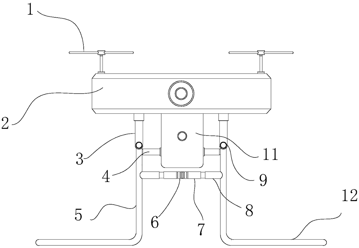
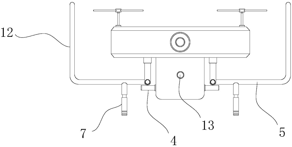
[0016] Such as figure 1 As shown, the movable landing gear of the multi-rotor UAV includes the UAV host 2, and four propellers 1 installed on the top of the UAV host 2. Airbag 11, an inlet and outlet air hole 13 is set at any position of the elastic airbag 11, and two connecting rods 3 are respectively installed on both sides of the elastic airbag 11;

[0017] The bottom of connecting rod 3 all offers a rotating chamber, and a support tripod 5 is all installed in the rotating chamber between adjacent two connecting rods, and the two ends tops of supporting tripod 5 are all rotatably installed in the rotating chamber, and the supporting tripod The bottom of 5 is provided with a bending portion 12, and the adjacent surfaces of the two supporting legs 5 are provided with two suction components, and both sides of the elastic airbag 11 are perpendicular to the hinges of the supporting legs and the connecting rod. Bond a push rod 4.

[0018] Both sides of the top of the supporting...


PUM


Abstract

The invention discloses a movable landing gear of a multi-rotor unmanned aerial vehicle, comprising an unmanned aerial vehicle (UAV) main engine and four propellers arranged on the top of the UAV mainengine, an elastic airbag is adhered and fixed at the middle of the bottom of the UAV main engine, an air inlet and an air outlet hole are arranged at any position of the elastic airbag, and two connecting rods are respectively installed on two sides of the elastic airbag; the bottom of the connecting rod is provided with a rotating cavity, a supporting foot frame is installed in the rotating cavity between two adjacent connecting rods, and the top of both ends of the supporting foot frame is rotatably installed in the rotating cavity. The unmanned aerial vehicle (UAV) of the invention uses the landing gear as the support and the protection, can use the bulging elastic airbag as the cushion for landing, saves the structure of the propeller protection bracket, reduces the overall weight ofthe UAV, does not use any electronic equipment, and does not increase the weight of the UAV.

Description

technical field [0001] The invention relates to the field of unmanned aerial vehicles, in particular to a movable landing gear of a multi-rotor unmanned aerial vehicle. Background technique [0002] A lot of propellers will be installed on the upper end of the main unit of the multi-rotor UAV. In order to prevent the propellers from being damaged by impact during flight, we will add protective brackets outside the propellers. Due to the large number of propellers, the number of protective brackets will also be corresponding. The use of such a large number of propellers will inevitably increase the overall weight of the UAV and reduce the endurance. In addition, the drone also needs to be equipped with a landing gear to support the use of the drone, and the setting of the landing gear also increases the overall weight of the drone, and the landing gear will cause certain resistance to the flight of the drone. Contents of the invention [0003] The technical problem to be s...

Claims


Application Information

Patent Timeline
Patent Type & Authority Applications(China)
IPC IPC(8): B64C25/10B64C25/32B64C27/00
CPCB64C25/10B64C25/32B64C27/006B64U10/10
Inventor 陈园婷
Owner 东阳市天齐科技有限公司
Why Eureka
Try Eureka